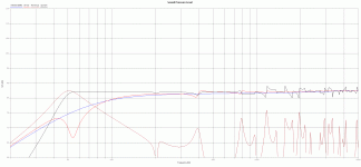
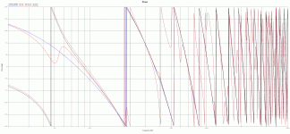
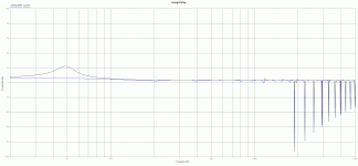
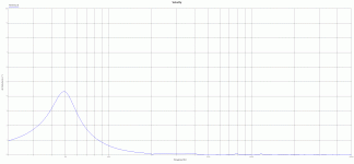
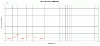
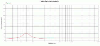
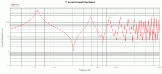
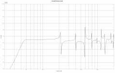
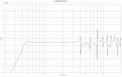
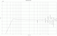
Here's my first enclosure design. It's an MLTL designed for the Mark Audio Pluvia 7 Full range driver. I'm going for a single driver speaker with no crossover, but will add a baffle step compensator if needed. I used the Leonard Audio TL program for the design. Please look over the model output and tell me what does or doesn't look good.
Also, I would love it if someone would put my specs in Martin's model and see if they get a similar result, or if it shows any "defects" in my design that the LA TL model doesn't detect.
Some of the model results are attached. I understand that the main goal is a flat SPL curve over a broad frequency range, but I must admit that I'm not sure what to look for in the other plots.
Okay, my MLTL specs are as follows:
Driver: Pluvia 7
Main Tube: 150 cm2 constant cross section x 87 mm long.
Driver Position: 42 cm
Port Position: 70 cm
Port Dimensions: 17 cm2 x 9 cm long.
Stuffing: Main tube from 30 mm to 70 mm only, density 3 kg/m3
Pluvia 7 Specs:
Revc= 7.200 Ohm
Fo= 67.863 Hz
Sd= 50.270 cm²
Vas= 5.543 Ltr
Cms= 1.545m M/N
Mmd= 3.356m Kg
Mms= 3.561 g
BL= 3.968 TM
Qms= 2.391
Qes= 0.695
Qts= 0.538
Levc= 35.057u H
No= 0.241 %
SPLo= 85.843 dB
Pwr= 22 watts
Nom X max= 4mm
1 way
FYI, all outputs were plotted with the default amplifier power of 1 watt.
Thanks,
Eric
Attachments
Greets!
Well, don't have MathCad loaded, but it's a bit too short to actually be a MLTL since its 1/4 WL tuning is too high to add any real damping to the vent and the driver is theoretically too low once damping is accounted for [MJK recommends 34.9% and I never go below 42% unless it's an expanding one, then down to 56% max], but otherwise as long as its T/S max flat alignment works for you in your app and its power limited tuning below Fs plays loud enough at your intended listening distance, then you're good to go.
GM
GM,
I really appreciate your reply, but as usual I need more help to understand (please bear with me!).
Can you clarify this for me? Isn't an MLTL normally short (compared to a classic 1/4 TL)? What do you mean by "damping the vent"? I thought the point was to mass load the vent, not damp it. I fear I'm missing your point entirely.
By too low, are you talking about the driver location (as a % of total length)? I've never seen that recomendation by MJK. Where does that come from? Is that in one of his published papers? Is it applicable to the MLTL? With the LA-TL simulation, adding damping (stuffing) doesn't seem to move the ideal driver placement much at all. I placed it where the LA TL model showed that it virtually eliminate the wiggle from the second overtone. If I chose the third overtone instead it would have been much higher. Is the MJK recommendation based on eliminating the second overtone?
Again, I'm not sure what exactly you mean. Are you basically saying only that it won't be capable of high volume, or are you saying more than that? What do you mean by "power limited tuning"?
Thanks,
Eric
I really appreciate your reply, but as usual I need more help to understand (please bear with me!).
but it's a bit too short to actually be a MLTL since its 1/4 WL tuning is too high to add any real damping to the vent
Can you clarify this for me? Isn't an MLTL normally short (compared to a classic 1/4 TL)? What do you mean by "damping the vent"? I thought the point was to mass load the vent, not damp it. I fear I'm missing your point entirely.
and the driver is theoretically too low once damping is accounted for [MJK recommends 34.9% and I never go below 42% unless it's an expanding one, then down to 56% max]
By too low, are you talking about the driver location (as a % of total length)? I've never seen that recomendation by MJK. Where does that come from? Is that in one of his published papers? Is it applicable to the MLTL? With the LA-TL simulation, adding damping (stuffing) doesn't seem to move the ideal driver placement much at all. I placed it where the LA TL model showed that it virtually eliminate the wiggle from the second overtone. If I chose the third overtone instead it would have been much higher. Is the MJK recommendation based on eliminating the second overtone?
but otherwise as long as its T/S max flat alignment works for you in your app and its power limited tuning below Fs plays loud enough at your intended listening distance, then you're good to go.
Again, I'm not sure what exactly you mean. Are you basically saying only that it won't be capable of high volume, or are you saying more than that? What do you mean by "power limited tuning"?
Thanks,
Eric
I'm not GM, but FWIW:
To a point. What GM's saying is that strictly speaking, most of the boxes that are described as MLTLs, aren't really using QW / standing waves at or around tuning. They're not physically long enough. So in such cases, what you have is a highly forced box where standing waves are occuring (and accounted for) somewhat higher up the frequency range.
See Martin's Classic TL Alignment Table pdf, for an untapered pipe. p.13, Driver Offset Ratio. Since an MLTL is an untapered pipe you can apply his same % ratio. You're not obliged to, obviously. It's just one of a variety of compromises to select from.
Basically, all drive units can only handle (and output) a finite amount of power. If you are satisfied this box and tuning can do what you want it to do, i.e. it will have sufficient power-handling & travel available to handle the average SPLs and dynamic headroom you want at your listening position, then job-jibbed: go ahead & build.
Can you clarify this for me? Isn't an MLTL normally short (compared to a classic 1/4 TL)? What do you mean by "damping the vent"? I thought the point was to mass load the vent, not damp it. I fear I'm missing your point entirely.
To a point. What GM's saying is that strictly speaking, most of the boxes that are described as MLTLs, aren't really using QW / standing waves at or around tuning. They're not physically long enough. So in such cases, what you have is a highly forced box where standing waves are occuring (and accounted for) somewhat higher up the frequency range.
By too low, are you talking about the driver location (as a % of total length)? I've never seen that recomendation by MJK. Where does that come from? Is that in one of his published papers? Is it applicable to the MLTL? With the LA-TL simulation, adding damping (stuffing) doesn't seem to move the ideal driver placement much at all. I placed it where the LA TL model showed that it virtually eliminate the wiggle from the second overtone. If I chose the third overtone instead it would have been much higher. Is the MJK recommendation based on eliminating the second overtone?
See Martin's Classic TL Alignment Table pdf, for an untapered pipe. p.13, Driver Offset Ratio. Since an MLTL is an untapered pipe you can apply his same % ratio. You're not obliged to, obviously. It's just one of a variety of compromises to select from.
Again, I'm not sure what exactly you mean. Are you basically saying only that it won't be capable of high volume, or are you saying more than that? What do you mean by "power limited tuning"?
Basically, all drive units can only handle (and output) a finite amount of power. If you are satisfied this box and tuning can do what you want it to do, i.e. it will have sufficient power-handling & travel available to handle the average SPLs and dynamic headroom you want at your listening position, then job-jibbed: go ahead & build.
Greets!
Yes, to mass load is to damp, but to be what I consider a MLTL requires enough 1/4 WL damping to either lower tuning [Fb] for a given vent alignment or shorten the vent to maintain a given tuning WRT a simple reflex/ducted port alignment, which this one doesn't do. In short, you have a BR with a very minor amount of 1/4 WL 'ripple' in its pass-band Vs a true BR that has none, so a minor amount of extra damping is required in comparison.
Yes, it's in his Classic TL Alignment Tables doc and if you learn a little more about TL design, at some point you'll realize that it will calculate MLTLs too. Assuming the vent is in the bottom 5th, his driver location chart applies close enough IME.
Correct/yes; if you look at an excursion Vs frequency chart you'll see that excursion increases by a factor of four/octave, so the lower the tuning the more rapidly its linear power handling capability is used up, i.e. at low distortion it will be very amp power limited with decreasing frequency, so for max linear power handling it ideally needs to be designed for a ~half octave above Fs tuning [~Fs*1.4142].
That, or design it to blend in with the room's gain curve to maximize peak power handling down to, or below, its Fs when positioned hard up against a wall or corner. Historically, most folks choose tuning around/at Fs as a compromise.
Your current alignment is normally used for when located well away from any room boundaries, which normally requires some baffle step compensation [BSC] to tonally balance its response over its entire usable band-width [BW]: General Speaker Related Articles
GM
I'm not GM, but FWIW:
Oops! Didn't notice your response till I was mostly finished, so posted a 'FWIW', FWIW 😉. Don't know why I bother to post anymore except 'off the cuff' 'quickies' nowadays since so many I start that interest me are either already sufficiently dealt with by the time I get back to them or they've gone elsewhere to get answers as has happened here.
From MJK's forum; guess I should 'check in' more often. I've disagreed with him enough on minor things to keep me from being one of his clique, though thought we were 'close enough' on the same 'page' acoustically to not be contrary, but apparently not.
I see there's some more responses to read, but got more important things to do right now.
GM
=================
Eric,
If I look at your SPL trace, and in particular the output from the port there is a strong fundamental peak followed by a roll off as frequency increases. In the rolling off SPL response there are also a series of peaks typical of higher order standing waves found in TLs. Looks like a ML TL response to me. Also in your acoustic impedance plot there are a series of peaks, a bass reflex design would only show a single peak at the tuning frequency of the enclosure.
The advice coming from DIYaudio has dropped in quality and accuracy over the years as a group of posters has started to dominate the discussion, in particular the full range sub forum. Many knowledgeable people left or stopped posting. Take what you read there with a grain of salt. That is my disgruntled opinion on DIYaudio.
Martin
-----Original Message-----
From: ekragness1@verizon.net [quarter-wave] <quarter-wave@yahoogroups.com>
To: quarter-wave <quarter-wave@yahoogroups.com>
Sent: Tue, Apr 5, 2016 12:00 pm
Subject: [quarter-wave] Re: How's This MLTL Look?
All,
Meanwhile, I posted the LA TL plots of my MLTL design on the Diyaudio forum, and got the response below from "GM". I'm sure much of it is accurate, but I frankly don't understand it very well. Can anybody translate his response to simpler terms? Please note, the design I posted was the same as the original design described at the start of this thread (with NO stuffing in the port), only stuffing from about 30 to 70 cm of the 87 cm overall length.
"Well, don't have MathCad loaded, but it's a bit too short to actually be a MLTL since its 1/4 WL tuning is too high to add any real damping to the vent and the driver is theoretically too low once damping is accounted for [MJK recommends 34.9% and I never go below 42% unless it's an expa nding one, then down to 56% max], but otherwise as long as its T/S max flat alignment works for you in your app and its power limited tuning below Fs plays loud enough at your intended listening distance, then you're good to go."
Probably to many of you this is all perfectly clear. But I'm not following....
Thanks,
Eric
__._,_.___
Hi Eric
My personal rules of thumb is to place the driver 1/3 or 1/5 from the closed end. Stuffing upper 2/3 of the pipe.
I would probably tune the cabinet a little lower.
The port: I use slottet port like TABAQ.
I will do some sims for you during the weekend.
And yes - the properties shows your design is a quarter wave.
Hi
Bjørn
Last edited:
Hmm. You & me both Greg -on both fronts. I'm only waffling by here when I can grab a few minutes, which seems increasingly rare. I haven't looked in at Martin's Yahoo group for a long time -I never could get on with the interface for some reason, & with limited time, I tend to stick to a couple of places only. Judging from what Martin's written, looks like he's classifying BR as pure Helmholtz (fair enough) & any departure as an MLTL, whether the standing waves necessarily impact on Fb or not. Looks like we're dinosaurs again. 😉 Oh well, I always did like the Brontosaurus.
Attachments
Last edited:
You mean Apatosaurus Ajax, perhaps? 😉
I mean now that Pluto is not an official " planet", let's just redefine everything we learned wrong in school 🙄
I mean now that Pluto is not an official " planet", let's just redefine everything we learned wrong in school 🙄
The advice coming from DIYaudio has dropped in quality and accuracy over the years as a group of posters has started to dominate the discussion, in particular the full range sub forum. Many knowledgeable people left or stopped posting. Take what you read there with a grain of salt. That is my disgruntled opinion on DIYaudio.
Martin
??? Is he grumbling that he cannot dominate the discussion here any more?
You mean Apatosaurus Ajax, perhaps? 😉
I mean now that Pluto is not an official " planet", let's just redefine everything we learned wrong in school 🙄
It would seem old Brontosaurus is back in business: https://en.wikipedia.org/wiki/Brontosaurus This makes me very happy. 🙂
Bjorn,
Thanks for your sim. It gives me a little greater comfort level with my design.
But I have some questions about your recommendations for driver position (at 33%) and port position (at the end). The LA-TL simulation seems to suggest that moving the driver lower and the port higher would provide a flatter SPL, as shown in the attached three figures.
The first figure shows the System SPL with the driver at 27 mm (33%) and the port at the end (SPL shown with no stuffing). Note that the SPL plateau drops a bit in the region above the 3/4 wave resonance (around 210 Hz), and then drops again above the 5/4 wave resonance at around 400 Hz.
But if I move the driver farther from the closed end to 42 cm (instead of 27 cm), I get the result shown in the second plot. Note that drop in SPL above 210 Hz is virtually eliminated by this relocation. However the SPL drop above the 5/4 wave resonance (400 Hz) still remains.
Finally, the third figure shows what happens if I move the port up to 72 cm (15 cm above the closed end). Note that now the SPL step at 400 Hz is also virtually eliminated, (as well as the step at 600 Hz), leaving the SPL curve virtually flat all the way up to about 800 Hz, with the exception of only a few narrow spikes.
So it seems, based on the LA-TL simulation anyway, that relocating the driver lower (to 41 cm) and the port higher (15 cm up), gives an even better response.
is this correct? Are the differences negligible? Are there good reasons not to make these moves based on other considerations?
I understand that the 33% driver location is the standard rule of thumb, at least for a standard TL. And this is based on the idea of placing the driver at the pressure node of the 3/4 wave resonance, which is located at 33% for a standard TL.
But I've noticed that the MLTL (like a converging tapered TL), "acts" like a longer TL than it's actual physical length suggests, so it makes sense (to me anyway), that the pressure node of the 3/4 wave of an MLTL would be farther down the line than for a standard TL. And the 41 cm location suggested by the LA TL model is exactly where the pressure node of 3/4 wave resonance frequency (210 Hz), should be.
Thoughts?
Thanks,
Eric
Attachments
Hi Eric
I have not done much sim moving the driver and port. From the beginning i had an idea of the final result: The opening at the bottom of the enclosure and the driver at the top.
I place driver 20 to 33 % from the closed end - except with my quarter wave sub where the unwanted harmonics dont matter.
The upper harmonics change according to the shape of the pipe. MJKs models does not care what kind of geometry you use. The models predict a result based on input.
I have simmed a 3" Tang Band in a 1.5 liter softdrink bottle, which of course needed pretty heavy stuffing due to the peaks. It sounded pretty good - fun to make.
I have used the same MJK model to sim be BR kit i build years ago, and MJK models documented why I did not like these.
In practise I do not try to design a loudspeaker with no ripples at all in the sim. The living room will change the SPL anyway due to reflections. However, I focus on not to have a flat deep bass, but a gentle roll off in the low end.
Hi
Bjørn
- Status
- Not open for further replies.
- Home
- Loudspeakers
- Full Range
- How's this MLTL Design Look
