Freedom of speech does not free you from questions being asked, or being told you are wrong. If you can't explain your posts, you might just consider not posting. You are also free to keep your thoughts to yourself...So pursuing this line of questioning is for what?
I'm done here.

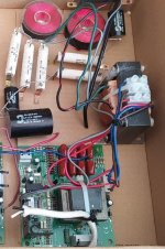
In addition to my previous comment on this crossover posted by the OP when he open up the back of the speakers:-
If you look closely you will note:-
1. There are several melt/burn marks into the "point to point" wire insulation from a soldering iron.
2. Several of the cables ties holding components to the board are very slack & are basically doing nothing.
3. Some of the soldering looks as if it is cracked, barely holding.
4. The wiring is badly routed/organised.
5. The "spare" unused ends of red coming from the 2core black cables are messy & have been altered from original?
6. Spacing of some components too close to one another (more an advanced technical point as commented previously)
Basically thats not left the factory like that, & the person who "upgraded" it has more enthusiasm than skill..
Yes, its good to encourage people to try things & "have a go", BUT when electricity is involved, skill/knowledge beats enthusiasm.......
If I was able to, I would encourage the original person who did the "upgrade" to note my above comments, correct the flaws & learn from their mistakes....You can make mistakes, & learn from them........unfortunately in some cases the mistake can be fatal & final!
I just wanted to learn why you think its junk, and this is your explanation? Not very convincing. Oh well.Perhaps it's because different people have different phrases and words for something.
That's called Freedom Of Speech in some cultures.
The attachment is correct. They have to be the right kind of perpendicular 😀That attachment is wrong. In contrast to the diagram, coils perpendicular to each other is a good idea.
It's a DIY speaker from the 70s...Basically thats not left the factory like that, & the person who "upgraded" it has more enthusiasm than skill..
Not very neat crossover and HV generator from a ML Aeon hybrid electrostatic still wired and laid out more or less as it was on the inside of the rear LF enclosure. Attached with silicon and wood screws. (these were unusual in having square slots.)
The pcb is the audio detector that activates the onboard HV generator section. The crossover seems to be a 2nd order @ about 450hz. Can only guess that the other inductors, capacitor and resistors are for levelling out the response.
LF unit is just a 2.5mh and 50uf cap.
The pcb is the audio detector that activates the onboard HV generator section. The crossover seems to be a 2nd order @ about 450hz. Can only guess that the other inductors, capacitor and resistors are for levelling out the response.
LF unit is just a 2.5mh and 50uf cap.
Attachments
It's a DIY speaker from the 70s...
Thanks.....that explains everything!!.... 😉

Attachments
True, i feel the same way.This site has become way too critical of the casual hobbyist. Years ago I found encouragement and welcoming "polite" comments that promote the hobby. Now the critic's snub their noses like they are professional designers who feel your submission is an insult to their self professed intellect!
But pointing out that two inductors are too close is not being snub, just trying to help.
Besides this thread is pretty much about nothing, since there was no real question in first post. Or did i miss it?
If you use capacitors rated for 400 or even 600 vdc, then obviously, they will be big. No surprise. One could use 100 volts rated caps and use spare cash for other stuff.
Especially if this is domestic high efficiency stuff seeing just few volts.
Btw, those expensive super big mp caps are basically two caps inside one, just double the value in series.
Square slots? Perhaps just a recessed square area? That would be a Robertson head, quite common in Canada.Not very neat crossover and HV generator from a ML Aeon hybrid electrostatic still wired and laid out more or less as it was on the inside of the rear LF enclosure. Attached with silicon and wood screws. (these were unusual in having square slots.)
The pcb is the audio detector that activates the onboard HV generator section. The crossover seems to be a 2nd order @ about 450hz. Can only guess that the other inductors, capacitor and resistors are for levelling out the response.
LF unit is just a 2.5mh and 50uf cap.
I managed to fit all these components onto a 5"X7" board.Those caps aren't all that big. Once you've dealt with 200uf/400v film caps, then you have some real estate to contend with.
We call them “ the keyboard warriors “This site has become way too critical of the casual hobbyist. Years ago I found encouragement and welcoming "polite" comments that promote the hobby. Now the critic's snub their noses like they are professional designers who feel your submission is an insult to their self professed intellect!
There is nothing on the underside of the peg board.Does the back of the pegboard look like this?
Well I’m not at all bothered by members slagging these off , they are after all an amateur build from the 70’s and the speakers themselves sounded very good .


I'd be worried about vibrations cracking some solder joints, because some caps are "flappin'around in the breeze"
Besides that, who cares how it looks. This thread sounds like WAF applies to internal components too. Can I get the resistors in teal? They're so much cuter!
Besides that, who cares how it looks. This thread sounds like WAF applies to internal components too. Can I get the resistors in teal? They're so much cuter!
- Home
- Loudspeakers
- Multi-Way
- How’s that for a speaker crossover