I have been away for a couple of days but I am following this thread with great interest.

Power ground from power supply to star ground making a power ground star ground point (isolated from the chassis), star ground connected to chassis ground via a "ground loop breaker circuit". Each board connected to star ground. Is it right so far Fast Eddie D?

Next up is signal path with shield/signal return/signal reference. I removed power feeds except the ground in order to de-clutter the image. Now it I get you right Fast Eddie D. RCA connectors isolated from chassis and shields connected together and routed to in your case the volume/balance/voltage amplifier board. In my picture it is the second board but it could have been the star ground point instead (it's pretty much the same in this context).
The shield on the cables connecting the first and second board is only attached at one end. The reason this works I guess is because signal pads for inputs and outputs are already referenced by the connection to power ground on the board. I guess the signal return will also be routed this way back to the common point for signal ground, is that right Fast Eddie D?
There will only be one ground connection per board as laid out in this example, the same goes for each RCA connector, and it would be the boards power ground (or a common star ground / power ground / signal ground). Right?

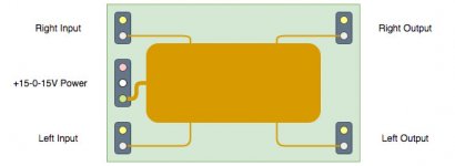
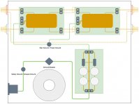
Let's see if I understand you right Fast Eddie D. I will use an imaginary preamp with more than one internal board. The board are also imaginary and I illustrate them like the picture below. They got signal and signal return/reference/ground pads for each input and output (both channels). It is single side boards with a common ground plane (signal reference connected through some copper pour/grounding scheme on board to power ground). The boards are powered by a +15-0-15V power supply.All audio grounds should return on only one end.
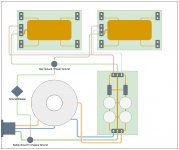
I also like a modular design. Below is a picture of the imaginary preamp with power attached to illustrate grounding scheme. AC in with safety ground firmly attached to chassis making a safety ground / chassis ground point. AC primaries are feed to a toroidal transformer and the secondaries to a power supply. Excuse my simplified drawings, no fuses and rectifier diodes etc. (it's all imaginary so you have to imagine them your self). I am just trying to highlight the ground path.I use modular designs for line level circuits so I can mix and match tried and true boards. The grounds on the boards are well parsed, and every board returns to ground in only one place - on the volume/balance/voltage amplifier board, right by the volume control ground. All RCA jacks return ground to this point as well. The power ground goes only to this board. The digital control board is grounded only at the power supply board. This is the only place the digital (noisy) and audio ground meet.
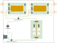
Power ground from power supply to star ground making a power ground star ground point (isolated from the chassis), star ground connected to chassis ground via a "ground loop breaker circuit". Each board connected to star ground. Is it right so far Fast Eddie D?
Next up is signal path with shield/signal return/signal reference. I removed power feeds except the ground in order to de-clutter the image. Now it I get you right Fast Eddie D. RCA connectors isolated from chassis and shields connected together and routed to in your case the volume/balance/voltage amplifier board. In my picture it is the second board but it could have been the star ground point instead (it's pretty much the same in this context).
The shield on the cables connecting the first and second board is only attached at one end. The reason this works I guess is because signal pads for inputs and outputs are already referenced by the connection to power ground on the board. I guess the signal return will also be routed this way back to the common point for signal ground, is that right Fast Eddie D?
There will only be one ground connection per board as laid out in this example, the same goes for each RCA connector, and it would be the boards power ground (or a common star ground / power ground / signal ground). Right?
Attachments
The signal flow and return should always be close coupled. Also you've shown the power supply 0V connected directly to the chassis
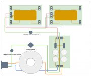
That is true! 😱 What about this instead?Also you've shown the power supply 0V connected directly to the chassis
I routed the RCA input and output shields/returns/referenses via star ground instead of the "volume/balance/voltage amplifier board" à la Fast Eddie D.
Still curious if this is a good representation of what Fast Eddie D was laying out? Shield between boards connected at only one end and with signal referenced and returned via each boards 0V wire to star ground (or directly to star ground for the barrels of the RCA connectors)?
Attachments
Last edited:
To minimize loop area? And if there is no ground loop?The signal flow and return should always be close coupled.
Last edited:
Yes, loop area between flow and return is important, think of any circuit with an enclosed area as acting like an aerial.
Eddie may have meant when using STP and connecting the shield at one end only.
I presume you've seen this too? http://hifisonix.com/wordpress/wp-content/uploads/2019/02/Ground-Loops.pdf
Eddie may have meant when using STP and connecting the shield at one end only.
I presume you've seen this too? http://hifisonix.com/wordpress/wp-content/uploads/2019/02/Ground-Loops.pdf
I was confused by the diagrams. I will try to explain my grounding technique in several installments.
I will describe the grounding technique in my preamp in several installments. My preamp consists of 1) A regulated power supply board with a ground loop breaker/safety circuit; 2) A volume/balance/voltage amplifier board; 3) Speaker frequency response correction board; 4) Bass and Treble control board; and 5) A digital control board.
I will describe the grounding technique in my preamp in several installments. My preamp consists of 1) A regulated power supply board with a ground loop breaker/safety circuit; 2) A volume/balance/voltage amplifier board; 3) Speaker frequency response correction board; 4) Bass and Treble control board; and 5) A digital control board.
Last edited:
Power supply board
On the board, the ground loop breaker circuit is grounded on one side to the chassis, and on the other side to the ground of the power supply board. The unit is mains powered and fused. It employs a three prong (grounded) plug.
There are only three ground wires connected to the board: the center tap from the power transformer, the signal ground from the volume control board, and the digital ground from the control board.
Control board
This board has both digital and analog grounds, which are isolated. The digital ground is connected to the power supply board. The analog ground is connected to the ground of the output jacks. This ground is only for shorting the output.
All digital grounds (relays and LEDs) return to this board.
This board has both digital and analog grounds, which are isolated. The digital ground is connected to the power supply board. The analog ground is connected to the ground of the output jacks. This ground is only for shorting the output.
All digital grounds (relays and LEDs) return to this board.
Volume/Balance/Voltage Amplifier Board
All audio grounds return to this board. There is a ground section right next to the volume control where all the wires connect. The power ground to the power supply board connects to this junction. This is the only power ground for all the audio circuitry.
All the RCA jack grounds are connected together on the back panel (isolated from the chassis, very important) and return to the volume control board with only one wire. This keeps ground currents associated with sources and the power amplifier localized and away from the electronic boards.
All shielded cable is grounded at one point only. All grounds must have only one return path, which must be clearly defined and controlled. I grounded the shielded input cables at the RCA jacks on the back. There is no ground associated with the input switch or input to the volume control board. Ground is referenced only through the single ground wire from the RCA jacks.
Other Audio Boards
Any other audio boards have only one ground lead, and it is connected to the Volume Control board. There is no power ground connection to these boards.
Digital and analog grounds on these boards must be isolated. Digital grounds must be returned to the Control board, never the Power Supply board.
It doesn't matter whether you put the Bass/Treble board or any auxiliary board before or after the Volume Control board. The grounding scheme works the same. In fact, putting auxiliary boards before the volume control will improve your signal to noise ratio at lower outputs.
A phono preamp or headphone amp each require on simple extra step, which I will describe upon request.
- Status
- Not open for further replies.
- Home
- Source & Line
- Analog Line Level
- How would you hookup RCA connectors?