I have been searching the net for information about the preferable way of hooking up RCA input and output connectors in a preamp. I have found a lot of general information about; safety ground, ground loops, chassis ground vs. signal ground, balanced vs. unbalanced, pin-1 problem etc. But surprisingly little when it comes down to actually hooking up unbalanced input and output RCA connectors. What little I have found also differs and that is why I would like to ask for feedback on how you do it and why?
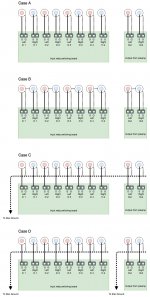
I have made a little sketch of an imaginary preamp. It got several boards inside where signals enter trough a relay based switching board. Each of the four inputs on the switching board got signal and ground connectors for each channel. The signal is switched and dispatched to another card with input buffers, yet another for filters and volume control etc. The signal is finally exiting through some output buffers on the board with the preamp outputs. I have outlined four different cases (based on information I have stumbled upon), A to D, as in the sketch attached below.
Case A, each input is connected separately to each input and output, the signal return and ground is probably carried in the shield of a shielded wire or as one of the leads in a twisted pair.
Case B, just as Case A but the RCA barrels of each couple of input and the output has been connected together.
Case C, is using a piece of wire as a ground bus shared by all inputs and outputs. The RCA ground bus connected to star ground and I assume any shield on the input and output cables terminated close to the RCA connector and not connected to the RCA ground bus.
Case D, just as Case C but with separate RCA ground buses for input and output.
Assumptions; all input and outputs are unbalanced, case connected to safety ground, RCA connectors isolated from the case, star ground available and connected to safety ground, all powered boards connected with power ground to star ground. Some boards with signal ground connected to power ground through a common ground plane on single side PCBs.
I know it would depend on the general grounding scheme and the design of the boards but in general, which one (A to D) would you prefer and why? If none of them what would you change and why?
Attachments
Last edited:
Case B because any cross-channel ground loops are kept within the preamp where they can be addressed
Thanks scottjoplin, that's how I done it but I would like to know if there is a better way (since I stumbled upon more than one way to do it)? And why if it does...Case B because any cross-channel ground loops are kept within the preamp where they can be addressed
There is generally no issues either way as there should be no current flowing to produce earth loop hum.
A (or a variation on B) would be interesting if you are either planning on switching both signal and ground (which can avoid ground loops involving multiple earthed source devices) or using balanced input stages to accommodate unbalanced signals as suggested by Bruno Putzeys. Something that, incidentally, I would definitely recommend looking at.
Many commercial designs are using a variation on C, mounting the jacks to the back panel serving as a star ground point. This avoids having to RF couple each single input ground to case (that's a lot of hand-soldered ceramic caps, potentially) and does well at not letting RF leak in.
Many commercial designs are using a variation on C, mounting the jacks to the back panel serving as a star ground point. This avoids having to RF couple each single input ground to case (that's a lot of hand-soldered ceramic caps, potentially) and does well at not letting RF leak in.
Neil Muncy (RIP) explained this almost 25 years ago. The shield/shell of any unbalanced interconnect circuit needs to be directly connected to the chassis.
Same thing goes for XLR balanced interconnects.
Same thing goes for XLR balanced interconnects.
So what you say is that the RCA connectors should NOT be isolated from the case and that the shield/ground/signal return (of unbalanced) should go to safety ground through the case (instead of via star ground), is that right?Neil Muncy (RIP) explained this almost 25 years ago. The shield/shell of any unbalanced interconnect circuit needs to be directly connected to the chassis.
Same thing goes for XLR balanced interconnects.
Ps. Makes me think about this thread...
Since you seem to have looked into it quite deeply, you may enjoy this thread Cable shield as a Faraday cage
I keep mine separate from the chassis, mounted close together with the grounds connected at the connectors. Power supply ground is also separate from the chassis/safety ground.
There are 3” of leads, are routed in the air, away from anything.
I thought I was doing good before with the board-mounted 1/4” headphone jack, but the slight hum that was there with that is gone now.
There are 3” of leads, are routed in the air, away from anything.
I thought I was doing good before with the board-mounted 1/4” headphone jack, but the slight hum that was there with that is gone now.
Thanks scottjoplin, I have read it before but it brings up another set of questions - if, when and where a shield should be connected, at only one end or both etc.Since you seem to have looked into it quite deeply, you may enjoy this thread Cable shield as a Faraday cage
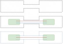
I have made a couple of new sketches. The first one, shield and earth in general.
The top sketch representing the schoolbook example of two closures where the shield of an interconnecting cable makes it into "one" shielded enclosure.
This is easy to grasp if you use for example a shielded twisted pair for unbalanced as in the next sketch. The shield can be attached to the enclosure and whatever earth potential it represents. The signal return has its own cable and can be attached to signal ground. Wherever they meet is another question.
But what about RCA connectors? They only got two pins so signal return and shield must be combined as in the last sketch making the enclosures signal ground, right?
Reading the paper Grounding and Shielding Audio Devices from RANE left me with another bunch of questions. It states for example:
RANE said:Unbalanced units connect successive signal grounds together directly through each interconnecting cable -- the sleeve of each RCA cable. This, and the fact that the chassis is generally used as a signal ground conductor, keeps the signal ground impedance of unbalanced systems very low. Many may agree that unbalanced systems are helped by the fact that the chassis are normally not earth grounded. This allows an entire unbalanced system to float with respect to earth ground. This eliminates the potential for multiple return paths for the audio grounding system, since there is not a second path (ground loop) through the earth ground conductor. Low signal ground impedance between units is essential for acceptable operation of all non-transformer-isolated systems, balanced and unbalanced.
The chassis normally not being earth connected - I assume they refer to Class II devices. But it leaves me with the question of unbalanced system left floating and what about non conductive enclosures like a plastic case?
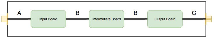
I have read all kind of statements and recommendations about the shield, mostly in the context of interconnect wires between enclosures (I have had a hard time finding material about internal wiring). Terminate it at both ends vs. leave one end floating etc. A common recommendation seems to be - connect both ends on inputs and only one end at outputs. If only one end is connected, connect it closest to the source etc. If the shield is efficient or not with one end floating is a question of its own but I would like answers to another set of questions. This talk about leaving one end unconnected, where does it apply? Have a look at the sketch below. It represents an imaginary preamp with RCA connectors for unbalanced inputs and outputs.
What about the input cabling (A in the sketch), shield connected at both ends or just one end? Connected to what if connected?
What about the internal cabling (B in the sketch), shield connected at both ends or just one end? Connected to what if connected?
What about the output cabling (C in the sketch), shield connected at both ends or just one end? Connected to what if connected?
Attachments
Last edited:
There is generally no need to use shielding inside a metal enclose so long as the external cable shields are terminated for RF where they enter. Have you read this? Audio Component Grounding and Interconnection I think it will answer most of your other questions
Yes I have but I will read it again. This time with my specific questions in mind. I just built a quite complex preamp (with integrated headphone amp, some filters etc.). I initially temporarily wired it internally with twisted pair cables from scrap CAT5 cables. I rewired everything when I was done sorting out board placement, grounding etc. I redid it with crimped shielded wires for inputs, outputs and between boards. I was surprised when I found it a tiny bit noisier with the shielded wires compared to the twisted pairs. I unfortunately didn't measure it before and after (it was just temporary) so it was just a case of perceived noisiness and it was on the RIAA input on full volume. But anyway, I did expect proper shielded cables for internal wiring to outperform cheap twisted pairs but that is not what I perceived (with reservation for not properly measure noise levels and just going by my ears).Have you read this? Audio Component Grounding and Interconnection I think it will answer most of your other questions
I was surprised when I found it a tiny bit noisier with the shielded wires compared to the twisted pairs.
I bet you actually wired it differently and created a ground loop. Typically shielded cable is connected at one end only.
Adding extra grounds doesn't help with noise at all; in fact it usually makes it worse.
Yes I wired it a bit differently and I attached both ends of the screen (as I used both pairs when using TP, one for signal and the other as return). I will check for ground loops (haven’t had time to measure and tweak it yet).I bet you actually wired it differently and created a ground loop. Typically shielded cable is connected at one end only.
Adding extra grounds doesn't help with noise at all; in fact it usually makes it worse.
Yes I wired it a bit differently and I attached both ends of the screen (as I used both pairs when using TP, one for signal and the other as return). I will check for ground loops (haven’t had time to measure and tweak it yet).
All audio grounds should return on only one end.
The most common mistake in modifying existing equipment is to create a ground loop. You have to know which side has to be grounded. In older equipment sometimes the original design includes a nasty ground loop. This is especially true of tube equipment pre 1960.
I use modular designs for line level circuits so I can mix and match tried and true boards. The grounds on the boards are well parsed, and every board returns to ground in only one place - on the volume/balance/voltage amplifier board, right by the volume control ground. All RCA jacks return ground to this point as well. The power ground goes only to this board. The digital control board is grounded only at the power supply board. This is the only place the digital (noisy) and audio ground meet.
This works for me. Not a click, thump, hum, hiss, static, nothing. No audible noises at all no matter what switches you throw. Completely black background. I believe this scheme would optimize even a circuit built with cheap parts.
You can't have "one end only" with coax - there are only two conductors in your cable - are you going to delete the signal reference at one end so you can leave the shield open at one end? How does your signal get to the other side?
Barring that impossibility, you can use shielded twisted pair and then connect the shield at only one end, but I'd prefer to connect the "open shield end" with a small RF grade capacitor (100nF or so) to the remote side chassis to make an RF ground. This is known as a "hybrid ground" system and it will do well to knock down RF but it will still leave the shield open at low frequencies.
A still better idea is to use a balanced, differential signal connection where there are two shielded signal wires of equal impedance, each carrying equal and opposite voltages and currents between the two devices. In this way, the net signal current between the two devices is zero, because the equal and opposite signals cancel completely. Since a net zero signal current is sourced to the remote device, and a net zero signal current is consumed by the remote device, the push pull signals completely cancel, and any ground connection between the two devices carries zero signal current.
In this case, it makes sense to connect ground solidly at each end of the connection - at this point, the shield (and ground) carries no signal current, and it behaves like a large chassis that encloses the entire system. With this structure, any additional metal added to the ground system, such as cable braid or additional chassis metal, will only serve to reduce the impedance of the "chassis" around the system, so it should be exploited as much as possible.
You can't have "one end only" with coax - there are only two conductors in your cable - are you going to delete the signal reference at one end so you can leave the shield open at one end? How does your signal get to the other side?
All RCA jacks return ground to this point as well.
To be specific, all the RCA grounds are connected together and return ground to the volume control ground with one wire.
In this case, it makes sense to connect ground solidly at each end of the connection - at this point, the shield (and ground) carries no signal current, and it behaves like a large chassis that encloses the entire system. With this structure, any additional metal added to the ground system, such as cable braid or additional chassis metal, will only serve to reduce the impedance of the "chassis" around the system, so it should be exploited as much as possible.
The "chassis ground" was used for signal ground in old tube equipment up until the 1950s. It was noisy and created multiple ground loops.
Chassis ground should be separated from signal ground by a ground loop breaker circuit. This consists of a 10 ohm, 5 watt resistor in parallel with two back to back diodes. This should be the only audio ground connection to the chassis. You must fuse the mains with this scheme. The fuse current rating should be equal to or less than the current rating of the diodes.
This is what I use. The preamp has a three pronged mains plug and so does the power amp. There are no problems with ground loops between preamp and power amp.
It works!
A still better idea is to use a balanced, differential signal connection where there are two shielded signal wires of equal impedance, each carrying equal and opposite voltages and currents between the two devices. In this way, the net signal current between the two devices is zero, because the equal and opposite signals cancel completely. Since a net zero signal current is sourced to the remote device, and a net zero signal current is consumed by the remote device, the push pull signals completely cancel, and any ground connection between the two devices carries zero signal current.
In a perfect world but you still have to parse your grounds carefully or else you'll introduce ground loops and noise.
Ask a licensed electrician about amateur wiring and "borrowing" a neutral for your bootleg circuit because "it's just a neutral." I guarantee you'll push a button.
All the problems you describe are evils of unbalanced circuitry. But, if you figured out some voodoo to make it work, then enjoy! I decided to skip it... much happier these days.
No voodoo or serendipity is involved. Commercial designers figured this out decades ago. Even a cheap $100 receiver with CD and other sources connected works without clicks, pops, thumps, hum, or ground loops.
Designing it can be a pain in the *** and one mistake can tank your efforts. But it works.
RCA jacks have been industry standard for at least 70 years. They are far from ideal for the task but as long as there's analog line level connections to be made they're never going away. It's great that you use balanced connections but they're just not universally applicable.
- Status
- Not open for further replies.
- Home
- Source & Line
- Analog Line Level
- How would you hookup RCA connectors?