I have downloaded the help file (and a chm file reader!) to look at the AKABAK 3 user guide from the website. The waveguide elements are lumped elements not boundary elements. The entry in the manual states the waveguide elements do not include any losses. Is your experience based on an older version, newer version, the manual is incorrect/out of date,...?
Even if the lumped waveguide element does include loss it can presumably only change the acoustic impedance of individual boundary elements. This isn't physically reasonable because the loss experienced by sound passing through stuffing will depend on the length of the path through that stuffing. For example, consider a case where sound travelling from a boundary element in some directions can miss the stuffing completely but in other directions takes a lengthy route through it (and neglecting the sound reflected back off the change in impedance at the air/stuffing interface). It isn't possible to both leave the level of sound from the boundary element unchanged while also heavily attenuating it.
One can probably do something rough and ready with lumped elements and/or 1D elements but it is hard to see a detailed 3D simulation based on a boundary element formulation being worthwhile in the sense of the substantially increased time and effort giving more accurate and detailed results. A coupled FEM for the stuffed region and BEM for the outside could work well but it is hard to see BEM alone or coupled to lumped elements working well enough to be worthwhile.
But it is a hobby after all and so if keen why not ignore the likes of me and have a crack?
Sorry it must be lumped element - I misspoke. It’s the old legacy 2.1 version that only runs on 16bit OS so you need a WinXP virtual machine. The damping is definitely there because TL’s without stuffing have some nasty output if no damping applied. I’ll see if I can whip up a script that shows this. If you can get a copy of the manual of the original Akabak, it will show it in there.
It’s located here:
Legacy Akabak 2.1
Download - Legacy Akabak 2.1
It’s located here:
Legacy Akabak 2.1
Download - Legacy Akabak 2.1
Last edited:
If you have the driver, start building and experimenting.
What's your target LR roll off?
I don't have the space yet but will quite soon. Target is around 300hz but lower is better
I have downloaded the help file (and a chm file reader!) to look at the AKABAK 3 user guide from the website. The waveguide elements are lumped elements not boundary elements. The entry in the manual states the waveguide elements do not include any losses. Is your experience based on an older version, newer version, the manual is incorrect/out of date,...?
Even if the lumped waveguide element does include loss it can presumably only change the acoustic impedance of individual boundary elements. This isn't physically reasonable because the loss experienced by sound passing through stuffing will depend on the length of the path through that stuffing. For example, consider a case where sound travelling from a boundary element in some directions can miss the stuffing completely but in other directions takes a lengthy route through it (and neglecting the sound reflected back off the change in impedance at the air/stuffing interface). It isn't possible to both leave the level of sound from the boundary element unchanged while also heavily attenuating it.
One can probably do something rough and ready with lumped elements and/or 1D elements but it is hard to see a detailed 3D simulation based on a boundary element formulation being worthwhile in the sense of the substantially increased time and effort giving more accurate and detailed results. A coupled FEM for the stuffed region and BEM for the outside could work well but it is hard to see BEM alone or coupled to lumped elements working well enough to be worthwhile.
But it is a hobby after all and so if keen why not ignore the likes of me and have a crack?
It will take me a few weeks to get my head around akabak at this point. I could try with a simplified version as attached...
Attachments
Is your goal cardioid response? I had an AE TD15M play well down to 125hz in a passive resistive enclosure and had cardioid like response up to 450hz IIRC. Above that response began to narrow. With a smaller woofer and waveguide loaded tweeter, cardioid like response from 300hz+ is doable. This thread may be helpful: 2-way: Waveguide + Cardioid-like
p165 of my old manual has:
AcouResistance Keyword
'...' Identifier
Node=s=t The acoustic resistance is between the poles s and t.
Ra=...Pas/m3 Value of the acoustic resistance.
Unit in Pascal seconds per meter 3 [Pa s/m 3 ].
See also: Impedance, AcouMass, AcouCompliance, Duct
AcouResistance Keyword
'...' Identifier
Node=s=t The acoustic resistance is between the poles s and t.
Ra=...Pas/m3 Value of the acoustic resistance.
Unit in Pascal seconds per meter 3 [Pa s/m 3 ].
See also: Impedance, AcouMass, AcouCompliance, Duct
Is your goal cardioid response? I had an AE TD15M play well down to 125hz in a passive resistive enclosure and had cardioid like response up to 450hz IIRC. Above that response began to narrow. With a smaller woofer and waveguide loaded tweeter, cardioid like response from 300hz+ is doable. This thread may be helpful: 2-way: Waveguide + Cardioid-like
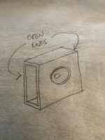
I'm hoping for the baffle to act as a waveguide for frequencies above 600hz. Below that the cardioid response of the open sides will hopefully take care of frequencies until the subs take over. I'm looking at 8" coaxial drivers from Faital Pro, Beyma etc for the mid/tweeter and 10" Monopole stereo subwoofers below.
Thanks for the link, I've been through it a few times but this design is different in the way that the rear wave path is instantly diverted (perpendicular to the driver wave front) in a tunnel rather than being absorbed at the rear and reflected back to the sides. I only have a crude mental model in my head of how this would play out.
Last edited:
I just looked up the Gradient Helsinki that uses same principal for midrange. Site says crossover for midrange is 200hz and 2200hz. So it is possible to get cardioid to 200hz with reasonably small baffle and open sides. I suspect the round baffle gives very even response off axis in vertical and horizontal. Looks like the driver offset and baffle angle is for beam "steering"?
Gradient Helsinki 1.5
Gradient Helsinki 1.5
- Home
- Loudspeakers
- Multi-Way
- How would I model this "enclosure" design? TL?