How would be a good proportional graphic of distortion for triodes ?
Are there some general rules to achieve the desired profile?
Use the Bias point in the symmetric part of the graph?
less or more current, more or less voltage?
Put the bias somewhere asymmetrical on the curve chart.
I read that may be, if the distortion is using the bias in symmetric curves, the 3rd harmonic and the 5th increase.
And putting the bias point on an asymmetric point of the curves graph gives 2nd and 4th order distortion.
I have doubts.
My amp sounds like a good Mosfet today, not a DHT.
I am using 6S45p and 6550 triode connection.
I bought a FFT spectrum analyzer, just to see how is the distortion pattern
today.
The chart below is just an example. It is not my amp.
Attachments
Typically falling harmonics, predominant 2nd order.
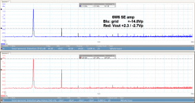
Here's an example of a 6W6 in SE, driven by a cascoded JFET. This is without NFB so the amp's gain is a bit high, it clips at only 330mV input level, so I can apply at least 12dB of NFB which will lower the distortion by about the same amount.
Blue trace is out of JFET/cascode driving the trioded 6W6 and red trace is out of amp into a resistive load.
Now show us yours.
Attachments
And its worth considering the two-tone intermodulation profile too. Intermodulation products are usually non-harmonic and more objectionable.
To answer the question, distorsion as low as possible.
Can you publish a schematic of your amp?
Attachments

Last edited:
47 µF bypass capacitor in stage S₁ is a bit low. It has a rolloff of
Using similar calculation logic, the bypass on the final
Testing the 100 kΩ pull-down ballast and the 0.33 µF
⋅-⋅-⋅ Just saying, ⋅-⋅-⋅
⋅-=≡ GoatGuy ✓ ≡=-⋅
PS... In the old days the engineering rule-of-thumb was '160,000 divided by microfarads and ohms'. But in reality the 160,000 is just an approximation of 1,000,000 / (2π) = 159,154.943. It is so much easier to type in 159159 on a calculator, as long as we're shooting for pretty-darn-good accuracy, anyway. Otherwise, the 160,000 value is also perfectly acceptable for these kinds of calculations.
F = 1/(2πZC) … or in µF and Ω
F = 159,159 / ZC
F = 159,159 / (47 µF × 50 Ω)
F = 68 Hz
, so significant roll off starts at 100 Hz. You probably don't want that. Using 470 µF lower this to 6 Hz, 220 µF at 12 Hz. Good down to 20 Hz, for sure.F = 159,159 / ZC
F = 159,159 / (47 µF × 50 Ω)
F = 68 Hz
Using similar calculation logic, the bypass on the final
F = 159159 / (330 Ω × 220 µF)
F = 2.2 Hz
A whole lot deeper into the infrasonic (LOL). F = 2.2 Hz
Testing the 100 kΩ pull-down ballast and the 0.33 µF
F = 159159 / (0.33 × 100,000)
F = 4.8 Hz
Pretty much on the dot. F = 4.8 Hz
⋅-⋅-⋅ Just saying, ⋅-⋅-⋅
⋅-=≡ GoatGuy ✓ ≡=-⋅
PS... In the old days the engineering rule-of-thumb was '160,000 divided by microfarads and ohms'. But in reality the 160,000 is just an approximation of 1,000,000 / (2π) = 159,154.943. It is so much easier to type in 159159 on a calculator, as long as we're shooting for pretty-darn-good accuracy, anyway. Otherwise, the 160,000 value is also perfectly acceptable for these kinds of calculations.
Last edited:
And its worth considering the two-tone intermodulation profile too. Intermodulation products are usually non-harmonic and more objectionable.
Oddly enough, by one of the great shams of electronic engineering, 'harmonic distortion' is anything but, in practice. It has been given the lovely title “intermodulation distortion”, but ultimately the distortion is not in the frequency domain at all: it is amplification linearity. ONLY when a not-quite-linear amplification curve is applied to a theoretically 'pure' sine wave, does the resulting output also have 'harmonic' distortion products, when FFT analyzed.
However, when even a computationally idealized 2 tone 'wave' is applied, ah… guess what … only in the case where the two tones are a small (n/m) ratio of each other (i.e. 'harmonic overtones') do the distortion products agree to nice little harmonic peaks in the Fourier ω plane transform;
Only then.
But when — as with real music source material — the actual composite waveform is a juxtaposition of dozens-to-hundreds of almost-but-not-quite harmonically superimposed overtones, well … in that case, with CAREFUL digitization and Fourier ω plane analysis, can one determine the so-called intermodulation distortion products are … nudge-nudge-wink-wink … themselves not even harmonically or “inter-harmonically” related to the source material. And they can be surprisingly large, too.
Such highly accepted analytic mendacity.
Makes the old physicist / mathematician / engineer / analytic programmer in me just fume.
Yet, … since I'm well past my restive 30's … since all of engineering rests squarely on coming up with both words-of-art and easily-digestible-conclusions, then what is more memorable than 'harmonic distortion' ideas?
Bizarre, what in turn the use of 'easy to conceptualize' mishandling does in a kind of chain-reaction therein. From the observation that asymmetrically nonideal amplifiers (such as no-feedback-compensated triode stages) do a fine job delivering suppressed 3rd, 5th, odd harmonds and enhanced 2nd, 4th and even ones (in theory, or is that the opposite? I never remember), then enthusiastic wags who have drunk The Kookaid and possibly theory-of-music coursework in University, go on to wax eloquent about how such harmonic distortion really ought to be viewed as musicality enhancement, which … ahem … in turn gives the “sweet signature of a valve amplifier over the stark and brittle embellishment of a solid state approximation” (that is a quote from a 25 year old Audiophile mag article!)
Bullsnot, actually.
Anyway. I felt the muse to write up an old grievance.
Done now.
⋅-⋅-⋅ Just saying, ⋅-⋅-⋅
⋅-=≡ GoatGuy ✓ ≡=-⋅
We have to stop playing musical instruments in air! It's an asymmetric non-linear medium for propigating sound pressure waves. Just look at the adiabatic compression curves. Looking at those curves makes the physical chemist in me cringe. 😀
If an amplifier behaves similarly to a musical instrument (increasing harmonics with increasing excitation) then all good.
To answer the question, distortion as low as possible.
Agreed, completely. I would add (or subvert?) a couple of ideals which I have found helpful in practice:
№ 0 — As linear as possible (the Prime Directive of amp technique!)
№ 1 — Except at either the – or + rail, where soft clipping is preferred
№ 2 — Except at the zero-crossing ± –30 dB level below peak-to-peak
№ 3 — … and ensure –3 dB below 7 Hz, –3 dB above 40 kHz
№ 4 — Do all this within an economical budget
№ 5 — And try hard not to use 'magic components' no matter how pretty.
That's about all. Each has its viable points. In practice some circuit part choices (or realities) actually deliver the special point(s) without requiring tedious engineering work-arounds.№ 1 — Except at either the – or + rail, where soft clipping is preferred
№ 2 — Except at the zero-crossing ± –30 dB level below peak-to-peak
№ 3 — … and ensure –3 dB below 7 Hz, –3 dB above 40 kHz
№ 4 — Do all this within an economical budget
№ 5 — And try hard not to use 'magic components' no matter how pretty.
For instance, № 0 is asymptotically achieved thru judicious use of very linear critical path components and significantly higher-than-strictly-needed gain and both local and global negative feedback axioms. However, the same LNFB and GNFB tend to work against № 1 and № 2.
№ 1 (soft clipping) is subjective, of course. But a not-abundantly-over-endowed vacuum valve final output stage tends to deliver 'soft' clipping. With 'soft' intermediary and line stages, the clipping can be even softer. 'Compression' is usually the word given.
№ 2 (subtle zero-crossing enhanced gain) is often hard to achieve in practice. It is however a reality for strict-triode stages, especially with fixed (or pseudo-fixed cathode-resistor-and-capacitor) bias schemes. No L-NFB, emphasizes the triode's native [ i(v) = vg³⁄₂ ] relationship, which without any 'corner' at all, delivers peak gain at zero-crossing point. Asymmetrically, unfortunately.
№ 3 (clamped bandwidth) just enhances stability, minimizes pass-thru of downwind signal issues. And optimizes parts-budget considerations.
№ 4 often goes unappreciated. Yet, it is a real consideration for many of us.
№ 5 is my personal foible. After a long, long life of actively using ABX (blind and double-blind) testing on components, almost all 'magic unicorn horn' devices fail to deliver what they promise. If we are building an amp tho' for a friend (or better, a client) who has gold-plated, titanium-lined, silver-soldered and non-GMO parts lust … well, get a hefty down pre-payment, and be very, very careful with the components. No mars, scratches, solder burns, oily fingerprints!!! Jeweler's fine-tipped, rounded shank pliers are a must.
Anyway… too much coffee, too much typing.
My apologies, if I offended anyone.
⋅-⋅-⋅ Just saying, ⋅-⋅-⋅
⋅-=≡ GoatGuy ✓ ≡=-⋅
santitrucco,
Your original question was:
"How would be a good proportional graphic of distortion for triodes ?"
Good? What do you mean by good?
Good sounding guitar amp; good sounding Hi Fi amp; good on the test bench, etc.?
Doing tests at 1 kHz on the bench with good equipment, including a non-inductive load resistor, may give you the following results:
1. A single stage of triode or single stage of triode wired output has one proportion of 2nd and 3rd harmonics, depending on the circuit parameters.
A typical stage might have 2nd harmonic 15 dB larger than the 3rd harmonic.
2. Now add a triode driver stage that has lots of drive voltage capability, and super low distortion, versus the output stage's required drive voltage.
You get almost the same distortion results as the original output stage by itself.
3. But instead, if the added triode driver stage has exactly the same relative proportion of harmonic distortions as the original output stage, what you get is:
Complete cancellation of the 2nd harmonic distortion, and an increase of the 3rd harmonic distortion.
4. Depending on the relative distortions of the first and second stages, you get the same results as the original single stage; complete or near cancellation of the 2nd harmonic distortion and increased 3rd harmonic distortion; or a mix that is something in between.
Well, what do you get when you connect that amplifier to a Loudspeaker?
You get different load impedances reflected to the output stage.
At some frequencies that impedance is purely resistive.
At some frequencies that impedance is purely inductive.
At some frequencies that impedance is purely capacitive.
At various frequencies, the impedance can be R, L, C, or any combination of those (1, 2, or all 3).
And the total impedance is different at different frequencies.
At some frequencies that are purely resistive, the resistance may be different
than when you had with the non-inductive load resistor during bench test.
That different reflected impedance creates a different load line on the output tube.
Whenever you change the load line (slope), both the amount of distortion, and the proportion of the 2nd harmonic distortion and 3rd harmonic distortion of the output stage changes.
And that now reacts differently with the driver distortions, which changes the total amplifier distortion, and relative 2nd and 3rd distortion levels.
And now it gets really complex:
For any frequency that the Loudspeaker impedance has some of either L or C, the load line is no longer a load line . . . instead it is an Elliptical Load (looks like an ellipse drawn on the tube family of curves).
And that really changes the harmonic distortion levels, both the total distortion, and the relative 2nd and 3rd harmonic distortion levels.
I like both single ended tube amplifiers, and push pull tube amplifiers.
But it should be noted that Class A push pull amplifiers are intrinsically better able to deal with elliptical loads (or overcome those elliptical loads better);
and single ended amplifiers have more difficulty with elliptical loads.
All this is especially true for push pull and single ended amplifiers that do not have negative feedback.
Negative feed back can somewhat help both of them to deal with elliptical loads, but single ended amplifiers still have a harder time at it.
"All Generalizations Have Exceptions" - Me
john_tracy,
I am sorry I do not know what adiabatic is, I should look it up, but am too busy now. adiabatic is over my head.
Perhaps it is the effect of distance from the sound source, such that higher frequencies (and therefore also higher frequency harmonics) are attenuated at a higher rate than lower frequencies.
Yes, that is not linear (unequal input versus output of various frequencies when the distance is longer rather than shorter).
In that case, we should all play our own acoustic guitars, in order to hear the proper relation of fundamental and harmonics.
I believe that air is a reasonably linear medium.
(as long as we are not talking about air pressure changes that are anywhere near levels that will cause our ears to bleed).
An acoustic suspension speaker is a good example of this intrinsic linearity. When sound is present, the air pressure in the box raises.
But . . . the spring action of the air on the woofer cone is linear over the excursion of the cone.
In High School Chemistry, I learned about STP (no, not a motor lubrication product; instead Standard Temperature and Pressure). That is a linear effect.
Of course my memory of what I learned then in 1962, may be suspect.
Last edited:
And regarding intermodulation distortion that is aggravated by having an elliptical load,
push pull amplifiers are intrinsically better able to deal with that load, versus single ended amplifiers.
"All Generalizations Have Exceptions" - Me
And sometimes, I like to hear some really non-symmetrical instrument sounds, like when the Jazz upright Bass player pulls the string away from the neck, and lets it "Whack" against the neck.
Nice sound effect!
Last edited:
Adiabatic refers to a closed system with no transfer of energy in the form of heat from the surroundings. Since air is a poor conductor of heat, it is a good aproximation.
> I do not know what adiabatic is,
I'm not sure that is the right word. But in context it seems to mean that we can compress air/gas as much as we want, but can not rarefy it past zero pressure. So the pressure/density function is inevitably *curved*, not unlike any tube/transistor, and all sounds are "distorted".
This becomes a BIG PROBLEM for sounds approaching 190dB SPL. 😱😱😱
It is a problem for horn speaker throats at high output.
It happens inside trumpets/etc; indeed a significant part of trumpet "tone".
If we insist on being silly, it is a problem in the ear, which IS a "horn" in reverse, long before the curvature is significant in the room.
But in context it seems to mean that we can compress air/gas as much as we want
For an ideal gas yes, but a real gas is made up of atoms and molecules that take up space and don't like being all squished up against each other. There is a limit. But since air is very dilute at one atmosphere assuming air is an ideal gas is a reasonable first order assumption.
What I was referring to is the asymmetric nature of the compression curve. This results in one half of the cycle being compressed and the other stretched. Classic second harmonic distortion.
John_tracy,
Would you please calculate the percent of 2nd harmonic distortion of air for a 1kHz tone at 90dB sound pressure level, at sea level, average barometer reading there, and 70 degrees F?
Until I know that answer I may not be able to sleep, because it may ruin my enjoyment of both live music, and played back music.
I know that my ear has 2nd harmonic distortion too, at that frequency, sound pressure level, at sea level, and when my body is a normal 98.6 degrees, with my Eustachian tube cleared out.
If an amplifier behaves similarly to a musical instrument (increasing harmonics with increasing excitation) then all good.
Could you explain how that would be good? As I understand that scenario the amplifier's harmonics increase with drive level so if I apply signal (recorded music) it will sound different depending on replay volume. A change in replay volume alone changes a lot already like e.g. excitation of room intercation(s) or the subjective excitation of the listener.
schiirrn,
I agree.
Saying that a flute has harmonics, does not make it good to add amplifier harmonics on top of that.
Here is another one:
Take an amplifier that has 1% 2nd harmonic distortion at a specified power out.
Take a loudspeaker that also has 1% 2nd harmonic distortion at the same power in as the amplifier is putting out.
Now you have more than 1% 2nd harmonic distortion.
Then, reverse the speaker + and - connections to the amplifier, you will cancel out the 2nd harmonic distortion, because the equal amounts are in opposite phase.
We tried that with a pure 100Hz sine generator, a 2A3 Amp, and a Spica 50 loudspeaker.
A double pole double throw switch was used to easily and instantly reverse the phase.
One person switched back and forth, back and forth.
The other person listened to the two different phases of the switch positions.
Then the two persons switched who did the switching, and who did the listening.
There were two different tonalities (timbres) to the 100Hz tone.
The idea was not to say which sounded better, but to see if it was easy to hear the difference in the tonality/timbre.
Yes, both people could easily hear the difference.
In my experience, an amp with lots of 2nd harmonic can make some music sound better in some ways. Plucked strings sound particularly nice to me.
Where it all breaks down for me is with music with a lot of stuff going on. Bass-heavy electronic music with vocals on top, for example.
Any amp with a transfer function that is not a straight line will create IM products when tones mix. When too many tones mix, the IM products start to noticeably sound bad. At least, I think that's what's going on. 😀
My push-pull amp can hit higher powers with very busy music and still sound very good. But Norah Jones sounds really good on my SE bench amp right now. Better than with my big push-pull amp.
- Home
- Amplifiers
- Tubes / Valves
- How would be a good proportion graphic of distortion for triodes ?