So do you endorse Doug's layout but reject mine?
I don’t reject/endorse any specific layout. I do it a specific way and have good results. However, if there are better/alternative ways of doing it, then I am interested in exploring those, thats all.
Well it's a figure of speech, I don't expect to see you on the morning news. I just want you to be more specific. You could just say "I didn't think much about it" and that would be fine with me, I don't scrutinize everything either.
I've been simulating along, and the differences I see between your presentation layout and the new layout are all under -110db relative to output, granted an idealized implementation. So it depends what your targets are.
I've been simulating along, and the differences I see between your presentation layout and the new layout are all under -110db relative to output, granted an idealized implementation. So it depends what your targets are.
The first PDF show just a hum breaking resistor, nothing else about the implementation.
The second PDF shows a balanced amplifier without a hum breaker, with unbalanced input source ground noise will be significant, and rejection of other hum sources will depend a lot on resistor matching and source impedance.
The second PDF shows a balanced amplifier without a hum breaker, with unbalanced input source ground noise will be significant, and rejection of other hum sources will depend a lot on resistor matching and source impedance.
I read Douglas Self's section again that relates to that graphic. He does recommend a connection from the star point to the mains/chassis ground. It's just not shown in the graphic.
_Please, do publish schematics ( lesser text ) and on those be clear about the physical implementation, give typical wire lenghts. Do not assume all that is obvious to you, goes obvious to readers.
Nothing new, but scattered here and there, reinvented over and over, in various ways. I wish you end up with THE reference way to do it, for Class AB audio amplifiers, once and for all.
_How much on board caps versus caps at the power supply do you recommend ?
Nothing new, but scattered here and there, reinvented over and over, in various ways. I wish you end up with THE reference way to do it, for Class AB audio amplifiers, once and for all.
_How much on board caps versus caps at the power supply do you recommend ?
I read Douglas Self's section again that relates to that graphic. He does recommend a connection from the star point to the mains/chassis ground. It's just not shown in the graphic.
In APAD6 he wrote:
Mains/chassis ground will need to be connected to the power amplifier at some point. Do not do this at the transformer centre-tap as this is spaced away from the input ground voltage by the return charging pulses, and will create severe ground loop hum when the input ground is connected to mains ground through another piece of equipment. Connecting mains ground to the star-point is better, as the charging pulses are excluded, but the track resistance between input ground and star will carry any ground loop currents and induce a buzz. Connecting mains ground to the input ground gives maximal immunity against ground loops.
The first PDF show just a hum breaking resistor, nothing else about the implementation.
The second PDF shows a balanced amplifier without a hum breaker, with unbalanced input source ground noise will be significant, and rejection of other hum sources will depend a lot on resistor matching and source impedance.
I don’t know which diagram you are referring to.
In APAD6 he wrote:
Mains/chassis ground will need to be connected to the power amplifier at some point. Do not do this at the transformer centre-tap as this is spaced away from the input ground voltage by the return charging pulses, and will create severe ground loop hum when the input ground is connected to mains ground through another piece of equipment. Connecting mains ground to the star-point is better, as the charging pulses are excluded, but the track resistance between input ground and star will carry any ground loop currents and induce a buzz. Connecting mains ground to the input ground gives maximal immunity against ground loops.
Quite correct. An HBR will help here, or his proposed method shown in the posted graphic a bit earlier.
But, he says very little about cross channel ground loops which I think are the most pernicious IMV.
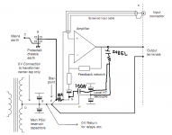
I modified the previous layout to show the difference in my layout in a way that is easier to compare.
Why is there a 100nF going to the input side of the HBR - did you mean to show it going to the on board decoupled junction?
Last edited:
_Please, do publish schematics ( lesser text ) and on those be clear about the physical implementation, give typical wire lenghts. Do not assume all that is obvious to you, goes obvious to readers.
Nothing new, but scattered here and there, reinvented over and over, in various ways. I wish you end up with THE reference way to do it, for Class AB audio amplifiers, once and for all.
Hear, hear. Bonsai's presentation already includes a layout that is probably good enough for most amps. This thread started because I proposed my layout and Bonsai wanted to move the discussion to a new thread. So really this is the research stage, I'm not 100% sure about my layout, hence the discussion.
_How much on board caps versus caps at the power supply do you recommend ?
My way of working this out is to compare the rectifier pulses to the haversines from the class AB stage. They are actually pretty similar. The rectifier pulses are sharper in general, but get shallower as power increases.
Therefore I think the a good balance is to have about the same amount of capacitance at the rectifiers as on the amp PCB. This means a minimum of currents will flow through the umbilical in either direction to reach the capacitors on the other side. But, most layouts don't give enough room for this amount of capacitance.
Why is the Zobel 100nF going to the input side of the HBR - did you mean to show it going to the on board decoupled junction?
That is where it must go to have the necessary effect. The capacitor is going to the board 0V point which in your presentation is where signal return originally connected.
Last edited:
Doesn't the Speaker return point influence on board cap size as well? I got the impression that the on board cap size needed to be relatively larger if the speaker negative was taken from the amp vs the power supply. This was discussed in the Bob Cordell's Power amplifier book thread starting at post #9208.
That is where it must go to have the necessary effect. The capacitor is going to the board 0V point which in your presentation is where signal return originally connected.
Sorry, I meant the cap marked 100n
I modified the previous layout to show the difference in my layout in a way that is easier to compare.
In your diagram, Self would argue you have any externally generated ground loop current across the 10R resistor
Doesn't the Speaker return point influence on board cap size as well? I got the impression that the on board cap size needed to be relatively larger if the speaker negative was taken from the amp vs the power supply. This was discussed in the Bob Cordell's Power amplifier book thread starting at post #9208.
If so then I would think it has to do with currents getting past the onboard capacitance and flowing into the umbilical.
It's actually quite hard to prevent audio currents from going through the umbilical. Adding a lot of capacitance to the board may reduce the HF umbilical current by half, usually less. It's a bit futile. It's much more effective to make the umbilical the R part of a CRC power supply, but this is another compromise as when currents flow back through the umbilical, they are reducing ripple on the board.
Sorry, I meant the cap marked 100n
That is the correct cap.


In your diagram, Self would argue you have any externally generated ground loop current across the 10R resistor
So you are saying the noise voltage between point F and board 0V causes a voltage drop across the 100nF cap and 10R resistor? That is correct. But, by your own admission the ratio of the currents through a 5mohm umbilical and the 10R resistor will be 2000:1. Add to that the capacitor, and you get an even smaller current, and only above audio frequencies.
I am still thinking about the capacitor. Not sure whether it's really necessary or whether it's the best way to address the problem.
Last edited:
- Home
- Amplifiers
- Solid State
- How to wire up an Amplifier