
Balanced-unbalanced - Balun
Does that help to figure out the wiring?
There are many examples on Google.
Jan
Does that help to figure out the wiring?
There are many examples on Google.
Jan
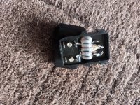
Yes I did, the wire is very thin, not sure but it looks like it is soldered to those blobs?
Basically it is just two windings, the primary connected to the incoming balanced signal, the secondary connected to the single ended/unbalanced receiver with one point grounded.
But to keep the impedances correct the number of windings is normally different. Do you know the intended impedances?
This for FM or TV?
Jan
Not what's in the pic, right.
But it seems pretty clear how to wire it.
The way it is shown confirms the 4:1 impedance ratio, 4 windings of 7 turn, two at each core.
In your case it is the ferrite core with two holes but that's also shown in the data sheet.
You should be able to construct that.
Two 7 turn winding at one outer side, then 2 windings of 7 turns around the other outer side.
Then wire to terminals as shown.
Or am I missing something?
Jan
BTW Are you familiar with those polarity dots on the windings?
They indicate same polarity, like 'start of winding' (or end of winding).
So at the top right, the start of one winding around the top core part would be connected to the start of winding of one winding around the bottom core part.
Those two wires would be connected to the single ended (unbal) output terminal.
Maybe good to verify if one of the output terminals is already hard wired to the metal of the thing, that would be ground (obviously).
The start of the two other windings should be connected to that ground.
If it is not hard wired, you can select your ground terminal as you wish.
Jan
👍
I'm no expert here but I believe that the number of turns also determines the impedance.
As far as I remember, 1/2 the turns is 1/4 the impedance. Maybe verify that.
Jan
I'm no expert here but I believe that the number of turns also determines the impedance.
As far as I remember, 1/2 the turns is 1/4 the impedance. Maybe verify that.
Jan
Too few turns causes the Insertion VSWR to rise at the low frequency end and too long a transmission line causes a steeper slope at the higher frequencies.
From the tiny wires in the balun it is probably an antenna (dipole?) for receiving, correct?
If so, do you need an impedance transformation of 4:1 (or 1:4)? A lambda/2 dipole has about Z=73 Ohm, which is almost ohmic. A dipole length L having Z = 300Ohm would be highly reactive (either capacitively for 0.25 lambda < L < 0.5 lambda or inductive for 0.5 lambda < L < lambda) (Source: 171ff in Balanis, Antenna Theory).
Is it then a voltage 4:1 balun or is it a 1:1 current balun for suppresing common mode currents? This is for me not exactly clear from the OP's first picture.
@jan.didden For a bifilar and symmetric winding the number of turns is at first site not relevant, but @baudouin0 mentions its impact on the usable frequency range (also not mentioned by the OP).
OK, thanks.
I thought this was for FM which is 300 ohms balanced (ribbon?), to 75 ohms coax.
BTW @baudouin0 = OP.
Jan
I thought this was for FM which is 300 ohms balanced (ribbon?), to 75 ohms coax.
BTW @baudouin0 = OP.
Jan
Its just a bog standard FM 300 to 75 balum. Originally did not work. If you look carefully both the input and output terminals are shorted with thin wires. I think some poor person is making these up without a clue on how to wire them up.
Regarding baluns you may have a look here:
https://content-files.shure.com/KnowledgeBaseFiles/troubleshooting-rfi-jim-brown-ham.pdf
or
https://www.dl4zao.de/_downloads/Balun_dl4zao.pdf (in German, although)
https://content-files.shure.com/KnowledgeBaseFiles/troubleshooting-rfi-jim-brown-ham.pdf
or
https://www.dl4zao.de/_downloads/Balun_dl4zao.pdf (in German, although)
- Home
- Amplifiers
- Tubes / Valves
- How to wire up a 4:1 balum