I am planning on using this switch as a selector switch in a pre-amp. I need help in how to wire the thing up. Planning 4 sources. I cannot seem to find any instructions online from the manufacturer. Any assistance would be appreciated.
Thanks in advance.
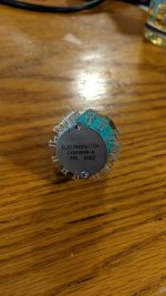
Electroswitch C4 series.
https://www.mouser.com/datasheet/2/128/c4-1730016.pdf
Thanks in advance.
Electroswitch C4 series.
https://www.mouser.com/datasheet/2/128/c4-1730016.pdf
Attachments
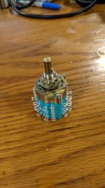
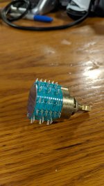
Hi you bought the wrong one it seems. For 4 sources you would need 4 positions/5 poles (always confusing) 2 decks.... You have bought a 9 pole 3 deck version but in true "anything goes" culture you can adapt it. First find out the main contact (it is described in the datasheet under PCB hole patterns) which will function as output to the volume control and then measure the contact that measures continuity when you move the switch 1 position. Repeat this when you move the switch 1 position and all decks will switch their contacts to the next contacts. Determine what function they will have and wire it up. So "CD", "DAC" , "DAB+" and the like. You can use the third desk to switch LEDs that will indicate the position. If you use those tiny 2 mm LEDs you can drill very small holes in the front cover and this will have a nice effect and you will always know which source is chosen even in a dark room. Choose a very low current for the LEDs to avoid being blinded and avoid blue LEDs as they look cheap and ugly. 2.5 mA is more than enough these days for green/red/yellow/amber LEDs. For pink/purple/white/blue LEDs you need to check their datasheets as they have higher Vf and may need higher currents.
Access Denied
Please note that using an analog switch with wiring means you will hear other sources faintly when they are playing. After you wired this up you will likely have a preference for input relays which exhibit this phenomenon way less. If you want quality you can use this switch to switch relays on an input PCB.
Last edited:
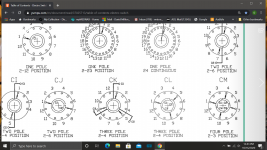
Thanks for the help. I figured it out at 0500 as I couldn't sleep ruminating it in my mind. The data sheet wasn't much help until I ran across this sheet buried somewhere on the internet. In the datasheet there was a reference for the "style" of the C4 switch is CK. Then on the attached sheet it becomes pretty clear what to do. Thanks for the help.
Further question: Why does this cross talk occur? Any improvement if you skip one position? So there would be an unused contact between used inputs.
Thanks in advance.
Dave
Further question: Why does this cross talk occur? Any improvement if you skip one position? So there would be an unused contact between used inputs.
Thanks in advance.
Dave
Attachments
Capacitive crosstalk in selector switches is typical, unless the unused inputs are grounded.
The cross coupling increases above around 1kHz, at a rate of +6dB/octave.
Not a real problem in most cases, just turn off the other sources.
The cross coupling increases above around 1kHz, at a rate of +6dB/octave.
Not a real problem in most cases, just turn off the other sources.
Thanks guys. This was helpful. I thought I'd use the third deck for grounds but I'll rethink that.
Hi, last year I wired a switch with GND's switched. Although I thought it worked OK I recently dug this device up and a friend wanted to try it out despite it being not 100% finished. He found out it has problems with GND potential differences. In his setup with exotic devices all GND except power amp are floating and since my DAC is a prototype/test device no PE connection was made (I know....). It is way less silent when switching SPDIF inputs and (it is a DAC) it looses "lock" many times after switching. Third negative side effect is that it is sensitive to static. Touching the input switch is also enough for the DAC to loose "lock". This goes to show that prototypes/test devices should not go to end users and that GND/PE stuff should always be done according safety regulations. In this specific setup there was 70V AC between GND's due to SMPS of one of the sources.
Probably the switched-off GND's must be referenced to GND by means of 100 Ohm resistors, GND must be referenced to PE and an input transformer should be used. Usual stuff for an experienced builder but this time persuasion won so to speak. Picked up the device the same day and haven't had the time to fix it yet. I have built many DACs and know having this working OK in other cases but maybe it is good to know that it does not always work out straight away in all situations. It can work OK provided things are done with care especially with regards to a GND scheme.
Probably the switched-off GND's must be referenced to GND by means of 100 Ohm resistors, GND must be referenced to PE and an input transformer should be used. Usual stuff for an experienced builder but this time persuasion won so to speak. Picked up the device the same day and haven't had the time to fix it yet. I have built many DACs and know having this working OK in other cases but maybe it is good to know that it does not always work out straight away in all situations. It can work OK provided things are done with care especially with regards to a GND scheme.
Last edited:
Capacitive crosstalk in selector switches is typical, unless the unused inputs are grounded.
The cross coupling increases above around 1kHz, at a rate of +6dB/octave.
Not a real problem in most cases, just turn off the other sources.
I'm about ready to wire the above switch up. I am still curious regarding crosstalk. Will crosstalk be reduced if I use the three different decks? One for each of the two channels and the third for the grounds? Or is this problem inherent in this type of switch?
Thanks
Yes, the farther physically apart the wiring is for the two channels, the less crosstalk, due to
lower parasitic coupling capacitance between them. Use either shielded cables, twisted pairs,
or single wires that are separated apart. Any ground wire coupling would be ohmic, so if possible
keep the ground wiring separate for the two channels until it is connected to the ground point.
This will also often reduce hum levels as well.
Some use low signal relays located at the best physical point in the circuit for audio switching.
The relays are then controlled by switches or ICs located elsewhere in the chassis. This will
remove the capacitive coupling problem entirely, except for the volume control, etc. where the
twp channels are still physically close together.
Last edited:
A separate volume control for each channel? Hope you have the preamp near the listening chair.
On the selector switch, since the shaft is round (no flat), you'll need two set screws to fasten
each end of the shaft, or things will loosen up quickly. The volume controls also. Like this one.
Shaft Coupler, for 6 - 6.35mm diameter shafts | Hifi Collective
On the selector switch, since the shaft is round (no flat), you'll need two set screws to fasten
each end of the shaft, or things will loosen up quickly. The volume controls also. Like this one.
Shaft Coupler, for 6 - 6.35mm diameter shafts | Hifi Collective
Last edited:
Yup, all set on both counts. Have remote with individual channel controls. I also have nice couplers from Khozmo. I'm hoping for the best here.
Yes, the farther physically apart the wiring is for the two channels, the less crosstalk, due to
lower parasitic coupling capacitance between them. Use either shielded cables, twisted pairs,
or single wires that are separated apart. Any ground wire coupling would be ohmic, so if possible
keep the ground wiring separate for the two channels until it is connected to the ground point.
This will also often reduce hum levels as well.
Would you suggest I run each of the grounds through the switch or just bring each one over to the ground bus?
I'm about ready to wire the above switch up. I am still curious regarding crosstalk. Will crosstalk be reduced if I use the three different decks? One for each of the two channels and the third for the grounds? Or is this problem inherent in this type of switch?
Thanks
Keep the input impedance low. If you use 500K or a meg at the input you will hear crosstalk. 25K won't be
much of a problem for most sources and will reduce Johnson noise (hiss) and EMI. Personally I shoot for
10K on my stuff.
G²
Would you suggest I run each of the grounds through the switch or just bring each one over to the ground bus?
I've never had the need to switch the grounds, so I just run them direct.
So my attenuators are 50K. What should I do to improve things?
Keep all the wiring short and direct, as well as separated between channels. More difficult cases
may require shielded cables or twisted pairs.
If your sources can drive 10k, you can parallel a 12k resistor with the input to the 50k pots,
to make the input impedance 10k.
Last edited:
Be sure to post some photos when it's all together and working.
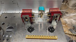
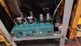
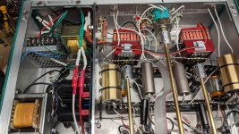
A couple of pictures:
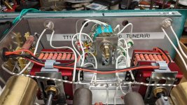
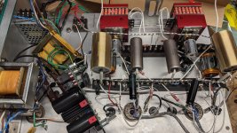
Need to chase down a bit of hum. I'm suspecting the attenuators which have a ground point as well as I've added a ground leak resistor of 1M.
Have to flip the display as well.
Sounds very dynamic and crystal clear.
Have to flip the display as well.
Sounds very dynamic and crystal clear.
Attachments
- Home
- Design & Build
- Parts
- How to Wire This Switch