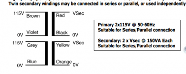
Yes, that is correct according to the figure.
The 230 V AC can then be applied between brown and blue. Black+yellow will be the centre tap of the secondary.
The 230 V AC can then be applied between brown and blue. Black+yellow will be the centre tap of the secondary.
would it also work similarly if I connect?Yes, that is correct according to the figure.
The 230 V AC can then be applied between brown and blue. Black+yellow will be the centre tap of the secondary.
- brown+blue
- red+orange
thanks
Yes, or brown+blue and black+yellow.
What you should definitely not do is to connect brown+grey or violet+blue. That would turn the transformer's primary into a poor type of short circuit.
What you should definitely not do is to connect brown+grey or violet+blue. That would turn the transformer's primary into a poor type of short circuit.
Last edited:
I am having a similar problem and I need some clarity as to how to resolve it.
I would like to use a power transformer that has two primaries (110v each) and two separate secondaries 22v @ 3A in such a way so that it works:
1) with US voltage;
2) and that I get 22v @3A on each tube by combining the secondaries in series.
So far, when I wired the primaries of the power transformer in parallel and put its secondaries in series, was able to double the voltage but only if the windings are in the proper phase.
Without any indication on the transformer, how can one determine/test for the proper phase of the windings?
I know that if the windings are out of phase they will overheat. (I assume that the overheating will not occur if there is no dc load on the secondaries. And by "load" I mean only dc load, correct? Putting a resistor across the a'c output of the secondaries doesn't count, correct? )
Please advise.
Thanks in advance.
If there's no color coding, the safest way is to use a few AC volts on the transformer primary from a signal generator,
set to around 50-100Hz. Connect the secondaries so the voltage across the series pair is maximum, and not near zero.
set to around 50-100Hz. Connect the secondaries so the voltage across the series pair is maximum, and not near zero.
Thanks.
Would I have to use a signal generator? Without one, can I use a few volts coming out of a variac with a dvm?
Would I have to use a signal generator? Without one, can I use a few volts coming out of a variac with a dvm?
There are never any foolish questions; the only fools are those who don't ask.
There is no universal system for identifying wires on transformers through the color of the wires.
There is no universal system for identifying wires on transformers through the color of the wires.
No, but a company is usually consistent for the ones they make.A foolish question: are these wire colors universal? All transformers follow that?
In the tube era, there was more standardization. Most amplifier power transformers had consistent
color coding. Even smaller transformers. There's no reason why it cannot be done today in most cases.
color coding. Even smaller transformers. There's no reason why it cannot be done today in most cases.
My question is that I remember that you can wire the input wires in series or in parallel, but you would have to use an oscilloscope to check the phase of the primaries, right? Any other simpler to check phase?
In that way for parallel you wire 0 to 0, and 115v to 115v. For series you should wires the "middle" 0 to 115v, but there I don't think you can do wrong, can you?
In that way for parallel you wire 0 to 0, and 115v to 115v. For series you should wires the "middle" 0 to 115v, but there I don't think you can do wrong, can you?
The primary windings must be paralleled in the same polarity, for sure. You can test that by driving them
with a few volts from a signal generator to be safe, if there's no reliable mfr color coding on the wires.
Then when you connect the secondaries in series, measure across the two outer wires to make sure they
add to twice the secondary voltage, but not zero.
with a few volts from a signal generator to be safe, if there's no reliable mfr color coding on the wires.
Then when you connect the secondaries in series, measure across the two outer wires to make sure they
add to twice the secondary voltage, but not zero.
- Home
- Amplifiers
- Power Supplies
- how to wire primary/secondary in series?
