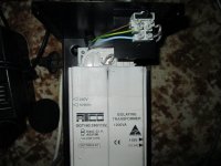
I want to have a pilot light on my isolation transformer so that I know if its on or not at a glance.I have a 90v neon light and a 270k ohm resistor to wire in series.It is a 240vAC to 110vAC transformer to power a 110v Sansui amplifier here in Australia where we have 240v The transformer didn't come with a switch at all,it is 6amps on the primary side so Ive got a 12amp,250v,DPDT for it.The switch shows continuity on the pins between 1 & 4 & 3 & 6. if I switch the toggle the other way its continuous between 2 & 5 & 3 & 6.The fuse is that black tag thing on the wiring block in the photo(brown wire is live)Any Ideas on how I can go about this,I keep tripping the fuses out and I'm sick of standing back when I turn it on with a broom stick LOL
Attachments
The lamp and ballast resistor should hook up easily between the hot and neutral lines.
Something is not right with that switch, though. You're showing continuity between 3 & 6 in both positions. Do you have a part number for it?
Something is not right with that switch, though. You're showing continuity between 3 & 6 in both positions. Do you have a part number for it?
The lamp and ballast resistor should hook up easily between the hot and neutral lines.
Something is not right with that switch, though. You're showing continuity between 3 & 6 in both positions. Do you have a part number for it?
I have a bridge soldered in between 2 & 5 and 3 & 6. I forgot to mention that,you see I originally asked this question on (All about Circuits) and I was advised to do that but when I mentioned the possible use of an LED the moderator locked the thread and chided me for not reading the fine print on 240v and LEDs?I think that site must be for children,run by children. Anyway I have the switch working by soldering the live wire to 3 & 6 and another to 2 & 5 that goes back to the connection/fuse block.The pilot light works as well but only when the switch is in the off position when I turn the switch on the light goes off? When I bought the neon light the catalog said that it is to be wired in series with a 270k ohm resistor,so Ive wired it the same as the live wire on the switch between 2 & 5 and 3 & 6 Its got me beat where the neon pins go? Just a thought,Do these neon lights have a built in diode and I have it soldered in backwards?
Last edited:
What you have is a double pole, double throw switch.
I would wire it so that it switches both active and neutral.
Firstly, remove the wire bridges.
Then connect the active to 2 and the neutral to 5 (you can reverse them, it doesn't matter)
The transformer is wired to either 1 and 4 OR 3 and 6 depending on which direction of the switch throw you want to be ON.
The neon goes to the same two terminals and no, there is no internal diode.
Put the fuse in series with the active on the mains side of the switch.
Last edited:
So you've made the DPDT switch into a SPDT switch? You've decided not to provide the part number? We're dealing with mains voltages here, so while some other forum may be overly cautious, some degree of care must be taken.
I have only a guess as to the pinout of the switch, especially the modified pinout, so I can't say for sure what's right or what's wrong. I wouldn't proceed without better certainty if the switch was in my hands, so I'm sure not going to tell you to.
I have only a guess as to the pinout of the switch, especially the modified pinout, so I can't say for sure what's right or what's wrong. I wouldn't proceed without better certainty if the switch was in my hands, so I'm sure not going to tell you to.
What you have is a double pole, double throw switch.
I would wire it so that it switches both active and neutral.
Firstly, remove the wire bridges.
Then connect the active to 2 and the neutral to 5 (you can reverse them, it doesn't matter)
The transformer is wired to either 1 and 4 OR 3 and 6 depending on which direction of the switch throw you want to be ON.
The neon goes to the same two terminals and no, there is no internal diode.
Put the fuse in series with the active on the mains side of the switch.
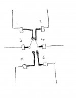
OK I have continuity between 1 & 4 and 2 & 5 with the switch one way and 2 & 5 and 3 & 6 the other way. I cant have the fuse on the mains side of the switch because the fuse is built into the wire connection block and it will be a hassle to change it, I thought I had better let you know that before I did anything. Do I still wire it how you said?
Are you sure ??
2 & 5 seem to be always connected, regardless of the operation of the switch and the other connections just don't make any sense.
Can you draw a little diagram as your description of the connectivity doesn't match any mains switch that I have ever met.
In my little drawing of a standard DPDT switch you would expect 3 to connect to 1. And 4 to connect to 2 in one position.
3 would connect to 5. And 4 would connect to 6 in the other position.
Attachments
Last edited:
Mains fuse should always come first.
That is the only way that all downstream faults can be isolated if some item shorts.
That is the only way that all downstream faults can be isolated if some item shorts.
The Mains Fuse always comes first.
The Mains Fuse rating must be LOWER than the smallest cable fed by that mains electricity.
The Mains Fuse rating must be LOWER than the smallest cable fed by that mains electricity.
I agree with K&D, there's something strange about that switch.
Can you give us a part or catalogue number and where you bought it from? Looks like sofaspuds concerns were justified.
Can you give us a part or catalogue number and where you bought it from? Looks like sofaspuds concerns were justified.
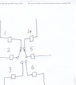
I don't have the part # for the switch,it was left over stock from a previous company(Dick Smiths) that was subsequently taken over, it is not in their catalogs and they don't have it anywhere. If you look at the original photo of the switch in an earlier post you will see that the numbering goes from top to bottom 1,2,3. and in parallel on the other side it says 4,5,6. Now you know what I was on about? So lets see if I have this right now? The pins on the neon go to the same place as the active wires go on the switch and it doesn't matter which pin on the neon light or the switch that the resistor is on? Going by the numbering on the latest diagram with the bridges removed I can solder the active wires to 1 & 2 or 2 & 3 in series,what is that 1 & 4 to 2 & 5 about? or then again 3 & 6 to 2 & 5, I only have the active wire to switch in case there is any confusion?The switch works when I solder the active to 1 & 2 or 2 & 3,but the neon works back to front! It is on when the switch and the power is off(yes I know power is still coming from the mains ) and it is off when the switch is on? I am confused now.How am I going to get the neon light wired in series so it works when it is switched on?
Attachments
Last edited:
Thanks for posting that diagram, it confirms what I and others had assumed about the switch configuration is correct. There is really no need to bridge the switch connections but lets go with what you've got.
OK, if you only want to switch the Mains Active lead, connect it to Pin 2 or 5. Connect one transformer lead to Pin 3 or 6. Let's call that Transformer Active.
Connect the other transformer lead to Mains Neutral.
Connect the neon indicator between the transformer Active lead and Mains Neutral. In other words it's between the two transformer leads.
Let's hope that your earlier fuse blowing episodes have not damaged the switch internally.
Last edited:
I think we're past that point unfortunately.in case there is any confusion?
Confirm that all your switch positions match the drawing in your post, please. You can see where continuity should be measured, and where it should be measured with the switch toggled.
Do you see how pin 2 is a pole, with pins 1 & 3 the double throw? And pin 5 is a pole, with pins 4 & 6 the double throw?
The resistor is connected in series with the neon lamp. That combination is then connected in parallel with the load, at the On side of the switch.
edit: Ah, OK. This is a drawing confirming the switch pinout, and Biblio is correct. The "load" in my last sentence is the transformer primary winding.
Last edited:
I think we're past that point unfortunately.
Confirm that all your switch positions match the drawing in your post, please. You can see where continuity should be measured, and where it should be measured with the switch toggled.
Do you see how pin 2 is a pole, with pins 1 & 3 the double throw? And pin 5 is a pole, with pins 4 & 6 the double throw?
The resistor is connected in series with the neon lamp. That combination is then connected in parallel with the load, at the On side of the switch.
edit: Ah, OK. This is a drawing confirming the switch pinout, and Biblio is correct. The "load" in my last sentence is the transformer primary winding.
The instant email notification doesn't seem to be working,Ive been sitting around waiting for an answer? I cant find the drawing that you referred to,did you post it? That would be a big help if you could post it again.
Hi Redrooster, do you find it?
The switch still can turn on & off right?
Why not take the wire connect to the trafo & just parallel the neon pilot lamp over there (the lamp series with the resistor). It is easy & simple
The switch still can turn on & off right?
Why not take the wire connect to the trafo & just parallel the neon pilot lamp over there (the lamp series with the resistor). It is easy & simple
- Status
- Not open for further replies.
- Home
- Amplifiers
- Power Supplies
- How to wire AC neon pilot light?