I'm wiring together a rackmount PSU to produce DC 18V +/- (bipolar). This PSU is going to be powering a guitar module that can handle up to 18V +/-.
The parts to make this PSU are:
(1) A transformer (AC 220 / 110V in 60Hz, AC 0-6/12/24V out 120mA out, 3VA max output):
1pc AC Power Transformer Input AC220 110V 60Hz Output AC6 12 24V 120mA 3VA | eBay
(2) An AC-DC regulator (AC/DC Input : 3-40V, Output Voltage : 1.25 - 37V Adjustable, Maximum Current : 2.2 Amp):
New LM317 Voltage Regulator AC DC in 3 40V Out DC1 25V 37V Power Supply Board | eBay
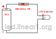
I am adding a power LED with specs as attached.
I am wondering how a power LED is wired up when it is being fed by a bipolar power supply. Do I feed the cathode off the 18 V + terminal of the regulator board (with resistor between)? If so, what do I attach the LED anode to? The 18 V - terminal of the regulator, or just straight to ground?
Thanks.
The parts to make this PSU are:
(1) A transformer (AC 220 / 110V in 60Hz, AC 0-6/12/24V out 120mA out, 3VA max output):
1pc AC Power Transformer Input AC220 110V 60Hz Output AC6 12 24V 120mA 3VA | eBay
(2) An AC-DC regulator (AC/DC Input : 3-40V, Output Voltage : 1.25 - 37V Adjustable, Maximum Current : 2.2 Amp):
New LM317 Voltage Regulator AC DC in 3 40V Out DC1 25V 37V Power Supply Board | eBay
I am adding a power LED with specs as attached.
I am wondering how a power LED is wired up when it is being fed by a bipolar power supply. Do I feed the cathode off the 18 V + terminal of the regulator board (with resistor between)? If so, what do I attach the LED anode to? The 18 V - terminal of the regulator, or just straight to ground?
Thanks.
Attachments
I am wondering how a power LED is wired up when it is being fed by a bipolar power supply. Do I feed the cathode off the 18 V + terminal
of the regulator board (with resistor between)? If so, what do I attach the LED anode to? The 18 V - terminal of the regulator, or just straight to ground?
Either way is ok, it's just a pilot light. Be sure to use the right resistor value to run 5-10mA with the voltage available, less the led drop.
Also, it's the anode that goes toward the positive supply.
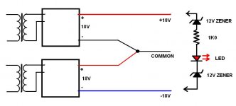
If this is what you are thinking of then I would connect the LED as shown. (you can sub a 24V zener for the two 12V zeners)
This way if either of the supplies quits the LED will not light.
If you don't want that feature then use a single 3K3 (3300 ohm) 1W resistor and the LED connected from +18V to -18V.
Hope that helps.
This way if either of the supplies quits the LED will not light.
If you don't want that feature then use a single 3K3 (3300 ohm) 1W resistor and the LED connected from +18V to -18V.
Hope that helps.
Attachments
Thanks guys. Follow up questions:
The drawing you attached DUG has two transformers and two 9V regulators. I'm just using the one transformer and one LM317 regulator PCB assembly to get my DC output. Should the setup I'm planning not produce a bipolar ouput (ie. +/- 1.25-37V adjustable)? Or do I need two transformers and two 9V regulators to do that?
Also the calculator I used in the OP attachment suggests I only need 820 ohms resistance. Is the suggestion of 3K3 just to tamp down the brightness a bit?
Last edited:
Okay I am now wondering based on the fact that it only has two terminals out from it (not 3, +/-/ground), if that means the regulator is probably unipolar.
Maybe if it is unipolar I will use this instead
1 25 37V Adjustable Voltage Regulator Module Based on LM317 LM337 | eBay
Maybe if it is unipolar I will use this instead
1 25 37V Adjustable Voltage Regulator Module Based on LM317 LM337 | eBay
Last edited:
I like the version with the Zener as Dug has drawn.
It lights up bright when full design voltage is available.
The light dims as voltage falls below design target.
By the time the 36Vdc has fallen to 26Vdc the light is completely out.
Don't run a 20mA rated LED @ max current.
2mA to 10mA is usually enough to get your attention.
A "flashing" LED is good where you need to know that voltage is getting close to a failure condition. Unfortunately the driver circuit to bring ON the warning LED is more complicated. A window comparator is one way to switch on after detecting low voltage.
Green for good voltage, red for bad voltage.
Based on the parts you picked if you want +/- XV and common then you will need two transformers and two regulators.Thanks guys. Follow up questions:
The drawing you attached DUG has two transformers and two 9V regulators. I'm just using the one transformer and one LM317 regulator PCB assembly to get my DC output. Should the setup I'm planning not produce a bipolar ouput (ie. +/- 1.25-37V adjustable)? Or do I need two transformers and two 9V regulators to do that?
...
Thanks guys. Follow up questions:
...
Also the calculator I used in the OP attachment suggests I only need 820 ohms resistance. Is the suggestion of 3K3 just to tamp down the brightness a bit?
The 3K3 was based on +/-18V (or 36V total)
(36-2)/0.01= 3K4 3K3 is close enough.
I use supply subtract 2V and divide by 10. That gives me Kohms...easy to do in your head and some people think you are smart 🙂
For supplies down close to the forward LED voltage I look up actual operating voltage at 10mA and use that.
As AndrewT says: 10mA is enough for LED's rated for 20mA.
You'll never calculate an ideal current because everyone's idea of how bright it should be is different. Modern high brightness types are good on only a few hundred microamps.

BTW... I wouldn't power the module right at its upper voltage range limit. It should work fine on +/- 15-16 volts max and provides a safety margin for voltage fluctuations.I'm wiring together a rackmount PSU to produce DC 18V +/- (bipolar). This PSU is going to be powering a guitar module that can handle up to 18V +/-.
Thanks all. Rather than use two transformers and two regulators, I'm going to buy a dual transformer and bipolar regulator.
I think this looks like a good regulator:
1 25 37V Adjustable Voltage Regulator Module Based on LM317 LM337 | eBay
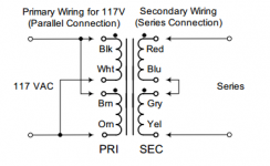
I'm looking at Hammond transformers since Mouser seems to stock them and they have a clear wiring guide. Their dual secondary transformers are here: Hammond Mfg. - Power Transformer - Dual Primary / Dual Secondary (266 Series)
Is my attached transformer wiring correct for North America for supplying dual AC voltage to the bipolar regulator above? If so blue and grey get soldered together and sent to regulator 0V input terminal?
Also, which Hammond would be good? I'm looking at 266F6 which is small and specs 1.89 VA, 6.3V @ 0.3A (series), 3.15V @ 0.6A (parallel).
I only need total maybe 30 mA at 9V +/- total for the LED and guitar module.
Thanks.
I think this looks like a good regulator:
1 25 37V Adjustable Voltage Regulator Module Based on LM317 LM337 | eBay
Code:
Input Voltage: Dual 4 to 32V AC
Output Voltage: +/- 1.25 to 37V DC
Output Current: 10mA to 1.5A
I'm looking at Hammond transformers since Mouser seems to stock them and they have a clear wiring guide. Their dual secondary transformers are here: Hammond Mfg. - Power Transformer - Dual Primary / Dual Secondary (266 Series)
Is my attached transformer wiring correct for North America for supplying dual AC voltage to the bipolar regulator above? If so blue and grey get soldered together and sent to regulator 0V input terminal?
Also, which Hammond would be good? I'm looking at 266F6 which is small and specs 1.89 VA, 6.3V @ 0.3A (series), 3.15V @ 0.6A (parallel).
I only need total maybe 30 mA at 9V +/- total for the LED and guitar module.
Thanks.
Attachments
Last edited:
You could put an LED/resistor between 18 volts and ground and -18 volts and ground.
This would show if one of the rails had gone down.
This would show if one of the rails had gone down.
You could put an LED/resistor between 18 volts and ground and -18 volts and ground.
This would show if one of the rails had gone down.
What if you only put it a single LED on ONE rail? Like between 18 V+ and ground? And nothing on 18V-?
In theory, would that create an asymmetric power draw from the + rail, and would that matter to the regulator? I know it's a tiny current for the LED but just wondering in theory if that matters with bigger current draw circuits ...
Also, is what Rayma suggested correct? Can I just go:
Code:
18+ V ===> resistor ===> anode [led] cathode ===> 18- Vand run it directly across the two rails?
You can put it across one rail.
Or across both rails.
Or one LED on each rail.
It doesn't matter about unbalancing the regulator, it wont care.
Or across both rails.
Or one LED on each rail.
It doesn't matter about unbalancing the regulator, it wont care.
You can put it across one rail.
Or across both rails.
Or one LED on each rail.
It doesn't matter about unbalancing the regulator, it wont care.
Good to know thanks. Any suggestions on my bipolar regulator and transformer question in the post above your first reply would be welcome also. As you can probably tell, I don't have any education in this stuff so I'd be lost without all your help. 🙂
Last edited:
A very small 0-9 0-9VAC 5 VA would do the job OK.
Use 7809 voltage regulators.
Loads of transformers and regulators at:
RS Components | Electronic and Electrical Components
Use 7809 voltage regulators.
Loads of transformers and regulators at:
RS Components | Electronic and Electrical Components
No, 6.3V is not enough. The peak voltage will only be about 9V; the regulators need to drop 2 or 3 volts to function correctly. Go with 9V instead of 6.3V. The 1.89VA is fine (at 9V that's 0.21A).
Yes, the transformer wiring is correct. The series primary connection is for 240V mains systems. And yes, the connected blue & grey wires will be ground.
Also, while I understand your inexperience I would mildly advise not to purchase the regulator board. You could build it on perfboard for far less than their asking price. Your application does not even require heatsinks for the regulators.
Last edited:
Every bipolar supply I build has three LEDs. The first is across the primary, and indicates the power is on. The other two are in series with the bleeder resistors across the filter caps. These are the "Don't Touch" lights, reminding me to keep my hands off until the caps are discharged.
I keep it simple every 12V I use a 1K 1/4W resistor. With a 2-3V drop for red/green/blue/white LEDS, it still leaves you 9-10mA.
1K 1/4W resistors are a dime-a-dozen, and it's just easy, and sufficient to just grab a 1K and use it for an LED for a no-brainer resistor drop in most projects.
Using a 7805 voltage regulator just for LEDS is too complex compared to a cheap resistor.
Also mentioned since you are running 18V supplies, two 1K resistors in series will be fine, or just a single 1.5K if you have it, but I usually have more 1K than anything else, so I just use those.
Exception is some LEDS that require more current like some Purple UV leds. (they look really cool in projects) I used 2X 560ohm in series for 19.5V Laptop SMPS, but a higher wattage 1K would have been just as suitable
Last edited:
- Status
- Not open for further replies.
- Home
- Amplifiers
- Power Supplies
- How to wire a power indicator LED from a bipolar PSU?