bloozestringer said:So, if my 273X is rated at 120VA, do I need to be using a larger amperage "bucking" transformer in your preferred configuration?
zigzagflux said:the total capability of this wiring configuration is 378 VA
It's really quite simple: Use a 37.8 VA transformer to gain 378 VA of total capacity. The 273X will be very happy with this configuration, no problems at all.
One other thing I should mention as an added bonus. Some have resorted to inserting resistors in the transformer primary to drop their voltage; this is certainly a valid approach (I do this with my RAKK DAC and tubed output stage). But a resistor adds significantly to the source impedance as seen by the circuit. An autotransformer has very low impedance, so ultimately changes your voltage and little else. It's the deluxe way to go.
If you don't have a need for a stiffer source or optimal voltage regulation, then a resistor is fine, just consumes a bunch of extra watts. The higher power your circuit demands, the more beneficial it becomes to use the autotransformer. I use an auto in my ST70, which was converted over to SS rectification. Helps drop the B+ voltage to the original design parameters.
zigzagflux said:It's really quite simple: Use a 37.8 VA transformer to gain 378 VA of total capacity. The 273X will be very happy with this configuration, no problems at all.
ZigZag, I've redrawn your pdf drawing. Could you verify that it is correct? I haven't had a chance to try this yet, but since I have two weeks off I'll give it a go before I move everything from the breadboard to the permanent chassis.
An externally hosted image should be here but it was not working when we last tested it.
zigzagflux said:Put the polarity dot on the other end of the 12.6V winding, and your drawing is correct.
Yep, you're right. Ooops. 🙄
Tried it this evening and it works great. Bucking trafo gets barely warm to be noticable and the 273X PT gets warm, but not hot in any way. Had 122.5V mains and was getting 108V from the bucking transformer to the PT when everything was under load. A little low, but it put the PT right at 350V per side, which put my B+ right where I wanted it as well.
Thanks a lot 😉
What about your 6.3v taps? if primary voltage is too low, it will affect these. I'm asking because I need to use this setup for several vintage amps.
If the 6.3V winding is loaded to its full 4A rated load, then he would expect around 6V output, which should be just fine. Assuming he has the 108V input feeding the 273X.
If the 6.3V winding is loaded at only 3A, you would find something higher, maybe 6.15V. Either way, the net effect is minor.
Running Hammonds a little on the lower end of 115V is a good idea, IMO. They tend to get quite hot over 120V.
If the 6.3V winding is loaded at only 3A, you would find something higher, maybe 6.15V. Either way, the net effect is minor.
Running Hammonds a little on the lower end of 115V is a good idea, IMO. They tend to get quite hot over 120V.
My 6.3V is only running the 5965 driver, so before I had the bucking transformer in I had to put a 2.7R resistor in series (I planned on splitting this with a resistor in each leg when fully done), and was able to get 6.1V (down from 7.3V). With the bucking transformer I'm getting 6.4V without any resistor at all except for a pair of 150R going to ground off the socket pins. I was also able to adjust my 1626 cathode resistor back to 1K which makes it easy to figure the bias on them.
My 1626's are running off a seperate filament transformer not included in the bucking setup.
My 1626's are running off a seperate filament transformer not included in the bucking setup.
Nice.
So 'splain this to me, am I gettin this right?
Since a 120v:12v transformer is a 10:1 ratio...
32VA becomes 320VA by multiplying the VA rating by the turns ratio. The 12.6v (or 6.3v section, which ever you choose to use) does not see hardly any current because it only has to drop 12.6v or 6.3v, correct?
zigzagflux said:The approximate short cut is to recognize a 10:1 turns ratio will increase its capability by 10 times
So yes, you gain approximately the same VA upgrade as the turns ratio. Not sure I follow your second question. The LV winding can carry up to its rated current, if the load is large enough to require it. For this particular application, the load is drawing very little, so the LV winding will carry very little. It is in series with the input.
Hi
Resurrecting this thread as I want to shave 10V off our UK mains, which in our area fluctuates from approx. 245-250V, so about 248V nominal.
As mentioned earlier I have a Dynaco ST70 which consumes 190W - so if I have this right that's approx. 0.7/5 - 0.8A consumed (at 248V).
Would this transformer 2 x 5V / 20VA be fine to use as a buck transformer please:
RS | Transformers | Transformers | Chassis Mounting Transformers | Chassis Mount, Clamp Construction, 230Vac, 6VA to 50VA |10-5857
I've been through this thread and sadly still remain confused as far as the amps/VA ratings are concerned. I know for the US the turns ratio can be used to roughly work out the 'buck' VA (i.e. 10:1 so a 20VA transformer would be 200VA wired for buck in the US). Do I follow that example but with 248V for the UK?
Thanks,
- John
P.S. The original buck transformer I used (on page 1 of this thread) worked perfectly, but it's since been used for a different project, and I want to get the Dynaco back out and working properly again.
Last edited:
Hi
Resurrecting this thread as I want to shave 10V off our UK mains, which in our area fluctuates from approx. 245-250V, so about 248V nominal.
The buck is simply connecting a transformer's secondary in series with the mains. So for a 1A capability you need a 1A secondary.
Then connect up the primary to make it work.
The polarity of the connection will either add or subtract the secondary voltage via the series secondary.
If you want to get rid of 12V, use a 12V transformer, probably a 12VA one.
Thanks for that. This 20VA tranformer is rated at 2A so I have a 1 Amp 'overhead' extra since the Dynaco uses approx. 0.8A. I just wanted to make sure it was safe, and this has put my mind at ease 😉
Ta,
- John
Ta,
- John
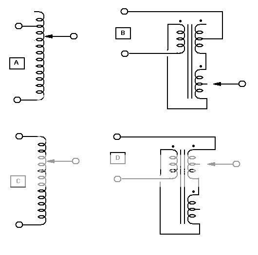
A) variac wired for boost B) dual 6 (or 12) VCT transformer wired for boost
c) variac wired for cut D) dual 6 (or 12) VCT transformer wired for cut
djk: you know those diagrams only have three terminals don't you?
johnm: Yesterday I wired up an old 24V 48VA transformer as I described to you, to shave 24 volts off my 245V mains, I now have a perfect 219V supply for my 220V stuff (and am actually using it now 🙂).
Just always check with a meter that you are getting the cut before connecting it to something valuable, and of course 'careful now' when playing with the national grid 😉
"djk: you know those diagrams only have three terminals don't you?"
I guess you might have a hard time hooking up a variac as well:
http://instrumentation-central.com/Staco/PDFCutSheets/vt100200.pdf
Yes, and if you can't figure out that the top left terminal is the line input, the bottom left terminal is the neutral, and the right terminal is line out, should you be wiring up any line power?
Last edited:
Sorry I thought the diagrams were for the OP!
I wonder why the common terminal is not drawn in - perhaps an ink shortage back then? 😉
Regardless, none of those diagrams match the buck wiring that I use, which is input mains to primary, output mains connected to input neutral, then output live via secondary in series from input live.
I'll try to post a picture later.
The diagram - as promised, dug up on the internet.
You should assume neutral is on the top and live is on the bottom. It doesn't matter of course, just a little safer to take some off the live and leave the neutral alone if you end up touching it one day.
Simply the secondary in series with the line, adding or subtracting it's voltage.
QED
You should assume neutral is on the top and live is on the bottom. It doesn't matter of course, just a little safer to take some off the live and leave the neutral alone if you end up touching it one day.
Simply the secondary in series with the line, adding or subtracting it's voltage.
QED
Attachments

Oops! I normally read everything left to right. Looking again at the schematic shown, if reading right to left as is was intended, it is correct. Sorry for any confusion.
- Status
- Not open for further replies.
- Home
- Amplifiers
- Power Supplies
- How to wire a 'Buck' transformer