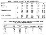
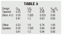
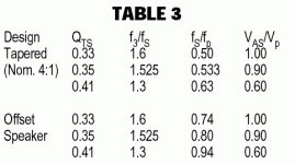
Bricolo said:Using the values from Table 2 (extended)..."
where's this table 2?
Augspurger has presented his paper 3 times, each in a slightly revised format. His original presentation at the 107 AES which i was present at, a 3 part Speaker Builder article, and then a revised paper in the AES Journal. The last is the one that i feel is most complete, but it doesn't have an "extended" table so i suspect the tables have been combined into the one below.
Note that the tables are quite sketchy with few data points and only show a small part of quarter-wave space. IMO Augspurger's work should be seen as background to help you wring the most out of Martin's software.
dave
Attachments
planet10 said:
Augspurger has presented his paper 3 times, each in a slightly revised format. His original presentation at the 107 AES which i was present at, a 3 part Speaker Builder article, and then a revised paper in the AES Journal. The last is the one that i feel is most complete, but it doesn't have an "extended" table so i suspect the tables have been combined into the one below.
Note that the tables are quite sketchy with few data points and only show a small part of quarter-wave space. IMO Augspurger's work should be seen as background to help you wring the most out of Martin's software.
dave
this is the optimized table
a second one exists, called extended table
I think it's the one in page 3 of joe's thor review (do you still have it?)
Bricolo said:joe's thor article
this article has a subset of the referenced table and it seems to cover lower Q drivers.
These tables still provide little detail for a line.
dave
Attachments
planet10 said:
this article has a subset of the referenced table and it seems to cover lower Q drivers.
These tables still provide little detail for a line.
dave
I just posted the same 😉
The Audax HM170G0 I plan to use has a 0.35Qts; so I don't bother the few data points, since the driver I want is exactly on a data point 😀
You say the table provides little data for a line, where can I find more data?
I mean fixed values; like augspurger's ones. Not like MJK's worksheets you use to "fine tune" a design based on augspurger's work (I plan to go this way)
another point: joe talks about a "corrected" Qts, extrapolated with the driver's Qts and the crossover
how can I calculate the total Qts of a driver and it's crossover?
how can I calculate the total Qts of a driver and it's crossover?
Bricolo said:You say the table provides little data for a line, where can I find more data?
I mean fixed values; like augspurger's ones. Not like MJK's worksheets you use to "fine tune" a design based on augspurger's work (I plan to go this way)
There is little data in between. Using Augspurger's tables will no doubt get you closer than a classic approach.
dave
planet10 said:
There is little data in between. Using Augspurger's tables will no doubt get you closer than a classic approach.
dave
 I think I don't understand
first, you say that there is little date in augspurger's table
then, you say that using augspurger's tables will give a good TL design
😕
Bricolo said:first, you say that there is little date in augspurger's table
then, you say that using augspurger's tables will give a good TL design
You put words in my mouth. I said it will probably give you a better design than a classoc approach, but not as good a line as one optimized in Martin's software.
Augspurger's table 1st limits you to a quarterwave subspace by limiting you to 3 preconfigured line "formats". Then using a sparse set of data points it gives you lines in a 3-dimensional space. Martin's software allows you continuous change thruout the whole of quarterwave space (ie what if the line worked better at a 6:1 taper, with an oddset, and a mass-loaded port?)
dave
Bricolo said:so, what are you calling a classical approach?
The Short Version. Then follow the link to the more detailed approach. I do not recommend building a line using this methodology... althou if you are looking to tune the line for flattest impedance Jon has some useful info.
dave
IMO, this is the complicated approach 😉planet10 said:
The Short Version. Then follow the link to the more detailed approach. I do not recommend building a line using this methodology... althou if you are looking to tune the line for flattest impedance Jon has some useful info.
dave
Dave, I think you can explain me:
In Augspourger's tables, what does the Qts mean? Is this the Qts of your driver, or the pipe's one?
some things made me thinks it's the TL's Qtsplanet10 said:the Qts of your driver
dave
cf pages 8&9 from augspurger's paper
I like Martin's tl worksheets but . . .
I could never understand why every driver I found to input into the open end tl file always works best, for low-end output, with a very large starting line. Atleast 3 times the Sd of the driver just like Martin's Focal that the file already has inputted in it. Any body else experience this?
I could never understand why every driver I found to input into the open end tl file always works best, for low-end output, with a very large starting line. Atleast 3 times the Sd of the driver just like Martin's Focal that the file already has inputted in it. Any body else experience this?
Pipe Size
The old wives tales of pipe with starting cross=sections of 1.5-2 Sd just won't die. I always start a simulation session with MJK's worksheets with So=4*Sd. Occasionally a pipe will work with 3*Sd, but not often.
Augspurger's tables really only work with large drivers with low Fs. Remember that Augspurger's method assumes Fp>Fs. So, if you start with a driver Fs=45, you are going to have a Fp and F3>50Hz. By using the mass-loading concept, you can design witn Fp<Fs. For exmple, my "Peerless Pipe" has F3=38Hz, even though the driver Fs=56Hz!
(However, if you do have a large, low driver and can stand a refrigerator sized cabinet, Augspurger's method can lead to a really impressive speaker. Of course, you can always get finer detail with MJK's worksheets.)
Bottom line: Unless you are using at least a 10" driver with Fs<30Hz, forget Augspurger, and please, let's never again mention the "classical method".
Bob
- Status
- Not open for further replies.
- Home
- Loudspeakers
- Multi-Way
- How to use Martin J. King's software to design a TL loudspeaker?


