The FORWARD and REVERSE current is controlled by the damper diode, because the vacuum diode OFF-time is faster, and its capacitance is lower.
Never quite understood the reason for 6CJ3. Much prefer the 6DE4 - octal socket, less heater current, lower capacitance, same dissipation, readily available.
For 60Hz rectification in tube amplifiers, we don't typically require a full blown 350mA rating, especially when you have two diodes per. Maybe a slightly better voltage drop, but the hassle of those sockets is just blech.
For 60Hz rectification in tube amplifiers, we don't typically require a full blown 350mA rating, especially when you have two diodes per. Maybe a slightly better voltage drop, but the hassle of those sockets is just blech.

How about as a damper diode, rather than a rectifier? Anyone try using them as flyback diodes on an audio amp? On some of my bigger stuff I put inverse-parallel silicon rectifiers across the plates for protection agains an open circuit secondary. Two UF4007 in series each has worked well in the past on 700 volt supply. But pushing the supply higher I might consider using vacuum state diodes, which would have a 5500V PIV rating (and a higher cool factor). Or would it be an issue to have zero cathode current 99.999% of the time?
There's also the Russian 6D22S, with its cathode brought out to a top pin. We've used a pair of these in parallel successfully as a starting ramp-up with 866s in a kiloVolt supply for 304TLs. No drama. Could very probably have just made them the rectifiers; certainly with a full bridge, but Iain was gungho on the Mercury. Kids, what can you do?
I bought a big box of 6AX4s years ago. Octal sockets, very affordable.
All good fortune,
Chris
I bought a big box of 6AX4s years ago. Octal sockets, very affordable.
All good fortune,
Chris
Last edited:
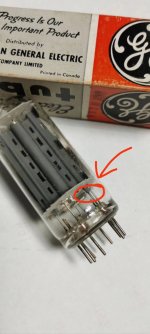
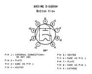
When I carefully observed the internal structure of the tube, I found that pin1 was connected to a white thread that seemed to extend from the inside of the heater. There was no special instruction in the manual, only that pin1 did not need to be used. I wonder if there is any hidden function?
Attachments
It's not a hidden function.
It's only an "internal connexion". It made the assembly process easier.
It is important to leave the IC pins open - not connected to anything.
It's only an "internal connexion". It made the assembly process easier.
It is important to leave the IC pins open - not connected to anything.
I wonder what you would actually need 3 internal connections for to make a diode. For sure you’d not want adjacent pins to see the A-K voltage. There really isn’t anything else to connect to.
There is no HK voltage limitation problem in damper diodes. 300 V heater positive WRT cathode is the condition of RECTIFIER CONDUCTING, under which cathode-to-plate voltage is internal voltage drop in forward direction, which is about 10-15 V for a typical DD under its rated steady current. In pulse applications the peak current could be about 3 A and internal voltage drop about 150 V (still within the allowable 300 V HK positive). In rectifier application, the positive HK voltage is way below the limit.
With this in mind, I've never had problem feeding heaters of the two DDs in a full-wave rectifier from the same 6.3 V winding.
With this in mind, I've never had problem feeding heaters of the two DDs in a full-wave rectifier from the same 6.3 V winding.
The application note recommends ripping unused pins out of DD socket. This is to prevent arching.I wonder what you would actually need 3 internal connections for to make a diode. For sure you’d not want adjacent pins to see the A-K voltage. There really isn’t anything else to connect to.
- Home
- Amplifiers
- Tubes / Valves
- How to use damper diodes correctly?