Hi everyone,
A friend just bought a 1970s oscilloscope for £5 - partly, he was thinking of me and my hi-fi habit!
Neither of us really have much clue about how to use it properly though. Can anyone explain the basics for trying to look at power supply line noise and ripple, or anything else that is useful to a DIYer/tweaker?
Alternatively, can you point me to a good BEGINNERS guide?
Do I need proper probes for it? It didn't come with any and I am using standard multimeter ones...
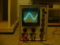
The 'scope itself is quite large, uses valves, and has two sets of inputs on the front. I can/will post a picture of it shortly.
I put it onto my homemade 5v psu and have managed to see a sort of lumpy sine-wave - is this AC ripple?
Thanks for any suggestions,
-Simon
A friend just bought a 1970s oscilloscope for £5 - partly, he was thinking of me and my hi-fi habit!
Neither of us really have much clue about how to use it properly though. Can anyone explain the basics for trying to look at power supply line noise and ripple, or anything else that is useful to a DIYer/tweaker?
Alternatively, can you point me to a good BEGINNERS guide?
Do I need proper probes for it? It didn't come with any and I am using standard multimeter ones...
The 'scope itself is quite large, uses valves, and has two sets of inputs on the front. I can/will post a picture of it shortly.
I put it onto my homemade 5v psu and have managed to see a sort of lumpy sine-wave - is this AC ripple?
Thanks for any suggestions,
-Simon
Here is a pic, showing what I found on my 5v psu. I guess the waveform shows AC ripple - I must need more than 5,000uf of smoothing!
How do I go about seeing 'noise'/RF/whatever on the line?
Might the scope not be sensitive enough for this??
-Simon
How do I go about seeing 'noise'/RF/whatever on the line?
Might the scope not be sensitive enough for this??
-Simon
i'm in kindof the same boat as you are. just got a used scope, want to figure it out. (if anyone knows where to find a cheap/free manual for a tek 2215a, lemme know...)
i just found this page on tektronix's website, it should help out a great deal. plus, it's in nice printable pdf format.
XYZs of Oscilloscopes
dig in... (or if you're the corny type: 'scope it out.')
/andrew
i just found this page on tektronix's website, it should help out a great deal. plus, it's in nice printable pdf format.
XYZs of Oscilloscopes
dig in... (or if you're the corny type: 'scope it out.')
/andrew
Hi guys,
I'm quite used to oscilloscopes. If you still need a hand after going through the guide in the link (in the post above), let me know 🙂
Jennice
btw.: To me this doesn't look like ordinary ripple... more like a scope picking up as an antenna (no good connection). Could you please post a new pic of that line distortion, with a description of your horizontal time axis (ms/div) and sensitivity (vertical, mV/div)
Andrew,
Thanks for the link, I will check it out when I get home tonight...
Jennice,
I will check what settings I used when I get home, again 😉
I think I had sensitivity on 5volts, but I'm not sure, I'll check. Not sure about the time setting... I'll look. Btw I don't think I get anything like that when the probe(s) aren't connected, I think it's somehow coming from my power supply. Why do you want a *new* picure of the distortion? Just as a repeat, for consistency?
Cheers guys,
-Simon
No, it should only be partially for reproduction/reliability. Itø's more the point that it doesn't look like the ordinary PSU hum/niose (unless you're working with a hard load on your PSU). 
Ooops... by the way...
You CAN risk getting something like that on your scope if one terminal (active) is connected. In that case, you can experience that the probe acts like an antenne, picking up 50 HZ field from nearby sources, such as your PSU leads or the transformer itself.
Jennice
You CAN risk getting something like that on your scope if one terminal (active) is connected. In that case, you can experience that the probe acts like an antenne, picking up 50 HZ field from nearby sources, such as your PSU leads or the transformer itself.
Jennice
faustian bargin said:
i just found this page on tektronix's website, it should help out a great deal. plus, it's in nice printable pdf format.
XYZs of Oscilloscopes
if you have a rainy afternoon when you can't go out and play, spending time on the TEK website will prove an educational treat --
one important thing on scopes -- don't skimp on probes -- no, you don't have to spend $300 on a probe, but a $40 10X/1X probe will make your measurements more reliable and understandable.
Jacki,
I agree that probes are a factor, but then again, the submitted scope picture had (as I understood it) a 5 V/div scale, and looking at a (hopefully) low impedance. This should, if everything is hooked up OK, provide a very low sensitivity to noise.
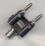
Btw., the scope does not seem to have BNC (shielded) input...
Jennice
I agree that probes are a factor, but then again, the submitted scope picture had (as I understood it) a 5 V/div scale, and looking at a (hopefully) low impedance. This should, if everything is hooked up OK, provide a very low sensitivity to noise.
Btw., the scope does not seem to have BNC (shielded) input...
Jennice
Jennice said:Jacki,
Btw., the scope does not seem to have BNC (shielded) input...
Jennice
Needs an adapter -- you can also pick up a HP Preamplifier (465?) 20 or 40dB of gain -- these go for around $20 on EBay (of course, that's more than the scope!)
Attachments
Not managed a new pic. yet, but here are the settings I used to get that wave..:a description of your horizontal time axis (ms/div) and sensitivity (vertical, mV/div)
x/time axis = 1ms/cm
y = 20volts/cm
Appreciate the comments Jennice and jackinnj - however, I do not want to invest much money into this thing. At least not until I know what I can usefully get from it! All I really want is to look at the quality of DC power - and if I can put it on the mains... well that would be swish, but it says 120v AC max 🙁
-Simon
Hi Simon,
If you're certain that Y=20V/cm, then you got a signal of approximately 90 V(peak-peak).
This really doesn't match with your statement about monitoring a 5V psu. Could it be that your division is 20mV/cm instead?
Byw.: It is possible to measure mains voltages using a resistive voltage divider. 🙂 Either use a probe, or DIY style, but make dure that the resistors can handle the voltage and dissipated power.
In the x axis you have 7 dividers for a cycle. With 1ms/div, that would give a cycle time of approx. 7 ms. This again equals a frequency of 140 Hz.
Considering that the scope is aged, it could possibly be explained as a 120Hz signal, but where would that come from? A harmonic of 60Hz mains?
Please re-check the connections to your circuit. I think the image still looks odd for a psu ripple image.
Besided, chech the oscilliscope for "adjust" buttons or screws, or "strech" buttons. Some scopes have ways to change the scale in steps that deviate from the fixed settings.
Also, it seems that you have a dual trace scope. This means that it has the ability to display two signals at the same time. Many scopes (especially older types) however, have a common signal ground, so make sure you don't create a short circuit.
See if the input terminals are marked A and B, or X and Y. X/Y modes are useful for checking phase between signals, but that's a different story 😉
If it IS a 2 channel scope, make sure that you display the channel that the probe is connected to. Otherwise, you'll most likely end up with a signal like the one on your scope, if it monitors a un-connected channel. See if you have a selection button dealing with "A, B, ALT" or something like that.
Jennice
Replies to Jennice
Hi Jennice,
Bearing these factors in mind, could I have been displaying a stretched ripple image? I will try again and see what I can get.
I appreciate your patience in helping me! 🙂
-Simon
ps "The Hi-Fi set is ok when you don't notice it's there..." -this is a good tag: it reminds me I still have a little way to go!
Hi Jennice,
Surely it must be mv then. It is 5v, I have measured it at 4.9v with my multimeter.If you're certain that Y=20V/cm
Yep, it has stretching knobs, and I had adjusted with them until I got the nicest looking and clearest wave. Next time I look I will try to leave them in the middle, is this correct?chech the oscilliscope for "adjust" buttons or screws, or "strech" buttons.
I was definately displaying the correct one! I 'pushed' the unused trace off the screen - and besides, it had no probes connected and would only display a flat line. Even with a probe waving around in the air, not much comes on screen (maybe it isn't all that sensitive).make sure that you display the channel that the probe is connected to
Bearing these factors in mind, could I have been displaying a stretched ripple image? I will try again and see what I can get.
I appreciate your patience in helping me! 🙂
-Simon
ps "The Hi-Fi set is ok when you don't notice it's there..." -this is a good tag: it reminds me I still have a little way to go!
Thanks for noticing the tag-line 🙂 You're the first one to comment on it... and yes, I too have some way to go (if I'll ever get there).
As for helping, I suppose that is what this forum is all about, except for occasional funny mis-haps and sarcasm. 😉
It sounds more likely to be a "mV" range. Still, you surely must have SOME load on it to abtain this ripple?
Regarding the adjustment knobs, there should be quite a few.
You'll probably find a focus and/or intensity adjustment to make the trace as clear as possible. Secondly (and probably near the sensitivity selector) you may find a variable adjustment for input sensitivity.
Near the "Time base" (X direction, speed of trace across the screen) you may find an adjustment knob to adjust it for auitable time base (mainly used to set a "reference" in grid units for verifying a specific time interval or frequency). Usually, such a time adjustment should be left in a "calibrated" state (often the far left or counter-clockwise position. check for labeling).
If you have a signal generator with a known frequency, then it may help you to do a one-time "household calibration" of the time base, after which you leave this knob alone. Otherwise you may want to display the voltage on the secondary of a transformer with a suitably low output voltage.
This will have a frequency ( 1 / "cycle time") which is rather accurate as your reference with 50 HZ or 60 HZ, depending on where you live).
Hope you'll find all my mumbling here useful...
Jennice
- Status
- Not open for further replies.
- Home
- Design & Build
- Equipment & Tools
- How to use an oscilloscope