I have a 2-channel tube amplifier. It does not have a subwoofer out. There's a sub I want that has both line-level and speaker-level inputs. Can I split the speaker outputs on the amplifier, so that both the speakers and the subwoofer are hooked up at the same time to the same speaker terminals? Or is that going to degrade sound quality or somehow hurt my amplifier?
Thanks.
Charles.
Thanks.
Charles.
It should be fine, just check that the output transformers are fully floating, i.e. one side is not grounded. Else when you common one side to ground at the sub and you get the wrong one you will have melted wires and hot transformers.
The only thing I would say coming from experience of this kind of setup before, is that the quality of bass you will get will experience from the sub will be a very poor representation of what is possible, because the early bass roll off of the output transformers and poor speaker damping spoils the LF signal.
The only thing I would say coming from experience of this kind of setup before, is that the quality of bass you will get will experience from the sub will be a very poor representation of what is possible, because the early bass roll off of the output transformers and poor speaker damping spoils the LF signal.
That's exactly the kind of information I need!
My tube amp is an integrated amp. I could open the amp and split the signal right after the master volume control, but before the first preamp stage, and wire that to a dedicated set of outputs for the subwoofer.
Would this be a better approach, or would I end up with the same problems?
Charles.
My tube amp is an integrated amp. I could open the amp and split the signal right after the master volume control, but before the first preamp stage, and wire that to a dedicated set of outputs for the subwoofer.
Would this be a better approach, or would I end up with the same problems?
Charles.
If you are happy doing that, the results would be a far better quality of bass. The only thing to watch is that driving possible long cables to the sub from the volume control, might alter the treble sound. Ideally the sub output would be buffered.
A buffer is an op-amp set up with unity gain to amplify the current of a signal, while the voltage stays the same.
This is to get the output signal from your preamp without loading it down. The buffer takes a small bit of current + voltage from your preamps output, and makes an exact replica of the signal, but with higher current and better drive - to send a good strong signal to your subwoofer amp.
This is to get the output signal from your preamp without loading it down. The buffer takes a small bit of current + voltage from your preamps output, and makes an exact replica of the signal, but with higher current and better drive - to send a good strong signal to your subwoofer amp.
Something like this? http://cgi.ebay.com/ws/eBayISAPI.dll?ViewItem&item=190209928110
Ideally, I'd like to hook up two coffee-table sized powered subwoofers on either side of my couch (and replace my coffee tables).
Eventually I might get a surround receiver, but for now music is my primary concern.
Charles.
Ideally, I'd like to hook up two coffee-table sized powered subwoofers on either side of my couch (and replace my coffee tables).
Eventually I might get a surround receiver, but for now music is my primary concern.
Charles.
If the preamp stage has a dual supply of the appropriate voltage I can build you a small buffer circuit (no charge).
I will build it and post a pic and you can tell me if you want it or not.
I will build it and post a pic and you can tell me if you want it or not.
OK, done. I was going to just P2P on a small proto board but my OCD got the best of me. I tested it on my system and bass is clean and plentiful.
OPA2134 buffer
Input impedance: 100k
Output impedance: 100R
DC offset Out_1: 1mv
DC offset Out_2: -1mv
OPA2134 buffer
Input impedance: 100k
Output impedance: 100R
DC offset Out_1: 1mv
DC offset Out_2: -1mv
An externally hosted image should be here but it was not working when we last tested it.
An externally hosted image should be here but it was not working when we last tested it.
Blimey, fast work!
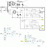
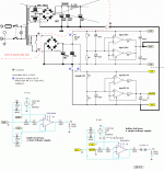
Can you put up a schematic? Looks like it has some output 'swamping' resistance but be nice to check.
Can you put up a schematic? Looks like it has some output 'swamping' resistance but be nice to check.
The buffer arrived the other day, and I just wanted to say thank you thank you thank you! This is a really nice small design... but I have a question. I really don't want to fry this thing, and although I've downloaded the datasheet for the chip, I'm still not 100% sure what to connect to where. I'd really appreciate it if you could tell me what the pinout of the 3-port and 5-port connectors are. Thanks!
Charles.
Charles.
Do you have somewhere in the amplifier you can tap into +/-15 volts (or more) to power the module? Or are you going to put it in its own standalone box? I would imagine a valve amp doesn't have any split rails you can tap into.
I'd like to put it inside of the amp, but chances are I'll have to build it into its own box.
15 volts or more? How much more? The chip is spec'd at 2.5 - 18V input. I was going to test it off of a couple 9V batteries (one for V+, the other for V-)...
Charles.
15 volts or more? How much more? The chip is spec'd at 2.5 - 18V input. I was going to test it off of a couple 9V batteries (one for V+, the other for V-)...
Charles.
Charles,
Very sorry, I meant to make up a wiring diagram and post it.
If you look at the first pic I posted above, the wiring goes......
(5 pos terminal)
IN_1, OUT_1, GROUND, OUT_2, IN_2
(3 pos terminal)
+V, GROUND, -V
Very sorry, I meant to make up a wiring diagram and post it.
If you look at the first pic I posted above, the wiring goes......
(5 pos terminal)
IN_1, OUT_1, GROUND, OUT_2, IN_2
(3 pos terminal)
+V, GROUND, -V
Sorry man, I can't read that diagram. I can follow simple instructions and solder pretty decent. I can replace components or make minor modifications. I can even build an amp from a kit. But reading and understanding schematics is beyond me, much less converting schematics into an actual device.
I haven't even looked inside the amp yet, and I don't really even know what voltages are availible... or how to get the required negative voltage.
Charles.
I haven't even looked inside the amp yet, and I don't really even know what voltages are availible... or how to get the required negative voltage.
Charles.
…I haven't even looked inside the amp yet, and I don't really even know what voltages are availible... or how to get the required negative voltage…
 Ok, You really need help and a lot of hands on, I suggest you find someone you know in person that can read and interpret simple cut and paste schematics like the one I posted. Updated picture: 1(1)
b
1(1)
Attachments
- Status
- Not open for further replies.
- Home
- Loudspeakers
- Subwoofers
- How to use a subwoofer with a 2-channel amp


