Hi All,
I'm developing a lithium ion charging circuit based on TI's BQ24618. After this part of the circuit there is the class D amp itself and the Bluetooth module. If you see the attached image you'll see I've added a switch so that the battery will always charge with an adapter attached but I can still turn the amp on and off.
I want to replace the switch (SW1) with a MOSFET and switch as it's going to be switching a decent amount of power and I want to be able to use a small switch or potentially a microcontroller in the future.
Anyway seems I'm really struggling to get my head round how this works. I was looking at N-Channel MOSFETS but this doesn't seem right as that requires the load (amplifier) to be before the MOSFET on the drain side. Would I use a P Channel MOSFET in this case? What would this circuitry look like?
Any help would be appreciated.
Thanks!
Attachments
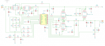
If you look at the circuit you'll see Q1/Q2/Q5 - these are already MOSFET switches controlling the power. They are pFETs since this is high-side switching.
It depends on the battery voltage and the peak current available. Consider your switch has to charge an empty capacitor of 1000uF for instance up to full battery voltage. What current peak is to be expected? Is the turn-on power-dissipation inside the SOA of your MOSFET?
These things get more tricky with rising battery voltage. Considering a 36V pedelec accu as a power source I would not even try this and consider alternative solutions.For instance my TPA3255 module has an on-board +/-12V flybuck converter that feeds the 12V-input of the TPA as well. Shutting down this converter at the UVLO-input disables the converter and the TPA, total current consumption drops below 100uA. Which is in the ballpark of self-discharge of the battery.
Just one idea😉
Last edited:
So that confirms it’s the P channel MOSFETS I need. I was just thrown by why there seems to be two of them at times connected to each other. If I use a P channel does my gate need to be a negative voltage?
- Status
- Not open for further replies.