I have got LM3886 but its not getting unmute.🙁
Please suggest Rm value for power supply of 18-0-18 dc.
When i disconnected Rm and left the pins untouched, there was only a little sound and that too even in max. input signal (full volume), indicating it to be in a mute condition.
I have seen datasheet and tried 22k, 10k, 5k,and 1.5k, but its still mute.😕
The rest schematics are according to figure1 of datasheet
CHANGES: replaced 22u with 47u and omitted Cm.
Please reply soon!
Umm.. is your mute switched on? lol...
You added a bit over 2x sized to feedback?
You need 2x less resistance between feedback and out...
I might be wrong.
You added a bit over 2x sized to feedback?
You need 2x less resistance between feedback and out...
I might be wrong.
I have got LM3886 but its not getting unmute.🙁
Please suggest Rm value for power supply of 18-0-18 dc.
When i disconnected Rm and left the pins untouched, there was only a little sound and that too even in max. input signal (full volume), indicating it to be in a mute condition.
I have seen datasheet and tried 22k, 10k, 5k,and 1.5k, but its still mute.😕
The rest schematics are according to figure1 of datasheet
CHANGES: replaced 22u with 47u and omitted Cm.
I would try with Rm 18k connected to V-. It should pass current over 0.5 mA for mute off, according to datasheet.
guys please help. I moved halfway across India to purchase two expensive lm3886 and now its not getting mute off. I placed ammeter in series to pin8, at Rm=5k, it showed 0.99 mA and at 1.5k it showed 1.42mA. But its not working either way. Accidently, I was holding sink with my hand and touched pin8, I heard a little DB gain in comparison to little sound at mute(pin 8 left opened n untouched) I have spend so much time and money that I m literally crying now🙁 Please help me!
Ahh, i wouldnt be crying over an amp chip. Tears are conductive...
I would redo the circuit exactly like it is in the datasheet and go from there.
I would redo the circuit exactly like it is in the datasheet and go from there.
are you sure its the only option? Bcoz its now same as datasheet. What you are saying is to redo the same thing and expect diff result. I can try it but by defination its insanity to expect diff result.
Isn't there any fault you can say about?
Isn't there any fault you can say about?
the mute pin needs current to go to "unmute".
The datasheet details the range of currents that are acceptable and shows what a reduced current will do in attenuating the output.
Yes, a reduced current works as an attenuator. It is NOT a switch between mute and unmute.
The datasheet details the range of currents that are acceptable and shows what a reduced current will do in attenuating the output.
Yes, a reduced current works as an attenuator. It is NOT a switch between mute and unmute.
guys please help. I moved halfway across India to purchase two expensive lm3886 and now its not getting mute off. I placed ammeter in series to pin8, at Rm=5k, it showed 0.99 mA and at 1.5k it showed 1.42mA. But its not working either way. Accidently, I was holding sink with my hand and touched pin8, I heard a little DB gain in comparison to little sound at mute(pin 8 left opened n untouched) I have spend so much time and money that I m literally crying now🙁 Please help me!
I have no experience with LM3886 but looks like Rm current is too small for +-18V and 5k value. Check GND (pin 7) as well as power supply pins.
Are you connecting Rm between pin 8 and V(-) as shown in the data sheet? The chip is in mute mode with pin 8 disconnected, there needs to be at least (-).5mA flowing into pin 8 to un-mute.
Mike
Mike
I have no experience with LM3886 but looks like Rm current is too small for +-18V and 5k value. Check GND (pin 7) as well as power supply pins.
i have made more complex amps using tda7386, tda7294 perfectly working in once
and am not sure i am doing this ic correct. HOW FUNNY is that!
Moreover as i mentioned, i checked the current using multimeter in series from Rm to -V. At 5K it showed 0.99mA, but still no sound. At 1.5k, 1.4mA current was read, still the same.🙁
Little worried if these are fake/damaged. But both ics showing same behaviour, i.e., at pin8 open, a little sound at full signal input whereas as soon its connected to -V via. 1.5K/5K/10K/22K, the little sound stops coming.
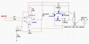
Here is the exact schematics I built.
Attachments
Last edited:
Does the non-inverting input have a dc-ground referance connection somehow? Schematic shows a single ground symbol which can't be right. There should be a separate ground path for: 1) input, feedback and pin 7 as a group, 2) power supply decoupling, and 3) speaker return and zobel. The power supply decoupling should be one small value ceramic disk (preferably COG/NPO) around 100nF with leads short as possible connected as close as possible to each supply pin and short path to common ground connection, and a medium size electrolytic (470uF to 1500uF) connected similarly with shortest possible leads.
Mike
Mike
Does the non-inverting input have a dc-ground referance connection somehow? Schematic shows a single ground symbol which can't be right. There should be a separate ground path for: 1) input, feedback and pin 7 as a group, 2) power supply decoupling, and 3) speaker return and zobel. The power supply decoupling should be one small value ceramic disk (preferably COG/NPO) around 100nF with leads short as possible connected as close as possible to each supply pin and short path to common ground connection, and a medium size electrolytic (470uF to 1500uF) connected similarly with shortest possible leads.
Mike
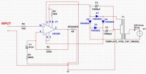
Oops, I had drawn so by mistake. Here is what i meant.
BTW, every diode is parallelly attached to 100nf. And i am quite sure this does not have any relation to the problem i am facing.
If i am missing something very important here, please at least draw me a rough sketch of modifications u recommend.
Attachments
Last edited:
Hi,
One thing that I noticed is that you are running both Lm3886 to the minimum permissible voltage allowed. I am running my at +/- 40 volts. I am not saying that running at +/- volts will not worked but it is a thought.
One thing that I noticed is that you are running both Lm3886 to the minimum permissible voltage allowed. I am running my at +/- 40 volts. I am not saying that running at +/- volts will not worked but it is a thought.
Hi,
One thing that I noticed is that you are running both Lm3886 to the minimum permissible voltage allowed. I am running my at +/- 40 volts. I am not saying that running at +/- volts will not worked but it is a thought.
I didn't get your point. please be specific.
You need a resistor from pin 10 (Vin+) to ground
are you sure that its responsible for no sound, because I m feeding input via. 100k analog controller
Once again, does the non-inverting (+)input have a dc-ground referance connection somehow? If there isn't a DC path for the input bias currents to follow, no, it won't work.
Mike
Mike
are you sure that its responsible for no sound, because I m feeding input via. 100k analog controller
Maybe your input is attenuated, try with resistor to gnd and another source.
- Status
- Not open for further replies.
- Home
- Amplifiers
- Chip Amps
- how to unmute LM3886 ?