I have an old tape deck with a non-functioning remote. Or rather I believe the remote control itself is working, but not the receiving end.
I don't have a schematic for the remote control, but pressing any button does produce an IR signal (verified by viewing the bulb through my phone camera). I've attached a snippet of the schematic for the board where the signal is sent. C901 and C903 both test fine out of circuit, as does R907. I'm going to remount the board and check for the expected 5V next. Assuming the voltage is correct, is there any way to test RC901 itself out of circuit?
I don't have a schematic for the remote control, but pressing any button does produce an IR signal (verified by viewing the bulb through my phone camera). I've attached a snippet of the schematic for the board where the signal is sent. C901 and C903 both test fine out of circuit, as does R907. I'm going to remount the board and check for the expected 5V next. Assuming the voltage is correct, is there any way to test RC901 itself out of circuit?
Attachments

Yes. It is easy with an oscilloscope. Without a scope, you can measure the center pin (output) with a digital multimeter. It should be 5V without remote control. It should go down a bit with a button pressed on the RC.
If you do not have an osciloscope you can conect a two anti-paralell LED serie with a 1-10uF capacitor and a 100 ohms resistor.
Other than trial an error and taking a chance on blowing it you really need an oscilloscope to check the digital pulses .
There are plenty of equipment on the web related to various manufacturers that talk about testing IR receivers relating to their own makes.
There are plenty of equipment on the web related to various manufacturers that talk about testing IR receivers relating to their own makes.
You can look at the optical output of any remote control with your digital camera. Phone cams are great
for this. Your scope on the data output of the IR receiver will show data with nearly any remote, The codes
won't be right and the deck won't respond but the IR receiver will show data. Receive modules are $1-$2 on
eBay and yes I have bought them and yes mine worked.
G²
for this. Your scope on the data output of the IR receiver will show data with nearly any remote, The codes
won't be right and the deck won't respond but the IR receiver will show data. Receive modules are $1-$2 on
eBay and yes I have bought them and yes mine worked.
G²
Quite correct Stratus 46--if it doesn't show digital type waveforms of any sort it is not receiving.
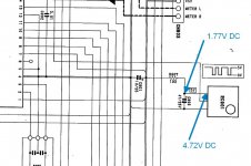
You are showing 2 different voltages on the same wire.Ok, I'm sure I'm missing something obvious with my scope settings, but I'm not seeing the waveform shown on the schematic when checking the output. With my meter, I get the following:
Impossible.
Recheck and remeasure and post results.
In last image is show a problem on power supply of sensor.
Check the capacitor C903 (replace it) and the voltage across R907. Voltage drop on R907 should be low, under 100-200mV. If it is higher replace the resistor and/or the sensor.
Check the capacitor C903 (replace it) and the voltage across R907. Voltage drop on R907 should be low, under 100-200mV. If it is higher replace the resistor and/or the sensor.
Last edited:
Use an Arduino & IR sensor.
Plenty of code on the web to translate any button press to a number.
Plenty of code on the web to translate any button press to a number.
In last image is show a problem on power supply of sensor.
Check the capacitor C903 (replace it) and the voltage across R907. Voltage drop on R907 should be low, under 100-200mV. If it is higher replace the resistor and/or the sensor.
C903 checked out fine for capacitance, leakage, and ESR. R907 is within tolerance. It would seem that the sensor is at fault here.
russc: I don't have any experience with Arduino, but I'll investigate further if I can't find an IR receiver that's a drop-in replacement for the original.
Here is an extremely simple IR receive sketch that I use to identify the number for a button press. The LG remote I
mostly use has a "repeat" character the same for any button press of 4294967295 which is FFFFFFFF hex
(32 bits, all 1) That is the only value it does NOT write to the "serial monitor" under "tools". As far as I know, you
can't upload a .INO file so I renamed it .TXT . This works with Samsung, Sony and Roku remotes and likely many
others. If it does NOT work it's possibly other than 38KHz modulation. To identify modulation frequency you'll
need a plain optical sensor and an oscilloscope to see ALL of the flashing light. You will find there are blocks of high
(30-50 KHz) frequency pulses with gaps between. The IR receive module shows you the envelope of the blocks and
only responds to the designed frequency.
The Arduino hardware consists of an Uno board with IR signal on pin 6, the Gnd and +5 on the power connector.
The readout is on the serial monitor, again under tools in the IDE. The Uno runs $5 to $10 in the States and only
needs a USB 2 port on your PC to power, program and read the serial monitor. The IDE is free at Arduino - Home
Genuine Arduino is around $25 US but the cheap eBay units are $5-10 US and they do work. I use both.
G²
Attachments
C903 checked out fine for capacitance, leakage, and ESR. R907 is within tolerance. It would seem that the sensor is at fault here.
russc: I don't have any experience with Arduino, but I'll investigate further if I can't find an IR receiver that's a drop-in replacement for the original.
So in the left side of R907 you have 5V (+/- something) and in the right side of it you have 1.8V?
You checked the resistor and it is ok? Put across it a 100-200 ohm resistor and check again. Replace the sensor if the voltage is still low.
The voltage across C901 is 5V?
Usually there are a lot of equivalent sensors available.
Maybe slightly of topic here, but allways usefull:
Point your remote at your phone's camera. You'll see whether the remote works or not.
Point your remote at your phone's camera. You'll see whether the remote works or not.
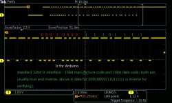
If RC901 is in normal operation, 2pin has standard Ir interface output like the attached pic. Ir transmitter for Arduino is an easy and inexpensive solution.
Gravity: IR Kit For Arduino-DFRobot
Gravity: IR Kit For Arduino-DFRobot
Attachments
So in the left side of R907 you have 5V (+/- something) and in the right side of it you have 1.8V?
You checked the resistor and it is ok? Put across it a 100-200 ohm resistor and check again. Replace the sensor if the voltage is still low.
The voltage across C901 is 5V?
Usually there are a lot of equivalent sensors available.
I just put a 100 ohm resistor across R907, and now I have 5V on the right side. Without the 100 ohm resistor, it goes back to 1.8V. So I pulled R907, and it still tests fine.
- Home
- Source & Line
- Analogue Source
- How to Test the Remote IR Receiver in a Tape Deck