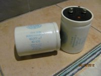
My antique dealer friend gave me these 60 000 uF cap for me to diy.
My cap meter only measure up to 20 K uf.
I intend to use it in a +/_ 22 v dc power supply for the Death Of Zen amp drawing about 3.5 to 4 amp continuously.
How to test these cap before using it ?
I do not have a ESR meter and any simple circuit to test it ?
thanks
kp93300
My cap meter only measure up to 20 K uf.
I intend to use it in a +/_ 22 v dc power supply for the Death Of Zen amp drawing about 3.5 to 4 amp continuously.
How to test these cap before using it ?
I do not have a ESR meter and any simple circuit to test it ?
thanks
kp93300
Attachments
Look up "capacitor forming" and do that to them first. Just to get them capacitating.
If you have a bench power supply use it, otherwise knock together a small power supply making 25-30 volts DC. COnnect a volt meter to the cap, and connect the power supply to the cap. That should charge the cap up to the supply voltage. Now disconnect the power supply from the cap. Monitor the meter to watch what the charge in the cap does. If it slowly drains away, that is a good sign. If it wants to just drop down fast and get out of town, that is no good.
Not very scientific, but no special gear required to perform this admittedly crude test.
Might be a good idea to put a small resistor between the supply and the cap incase the cap shorts (sometimes happens) The resistance large enough to limit the current to below the max supply current, it will also prevent the large inrush currents that a supply may not like to see.
If you want to really test it, there's a quick cap bridge that also does losses here that will go to 100,000 uF and just uses a few components. You could also measure the charge time with a known resistor and calculate the value. If you download Visual Analyser (free- Google it), it has a full LCR meter built in. All you need is the right interface to your sound card. Not sure how high it reads. They look like Sangamo. If they're old, check the leakage as well. Chances are they're good.
Can't you could put another smaller known capacitance cap less than 20,000uf in series and re-measure total capacitance with your LC Meter??
1/Ct=1/C1 + 1/C2
EDIT - It's been a while, and I think I got that right.
1/Ct=1/C1 + 1/C2
EDIT - It's been a while, and I think I got that right.
Last edited:
As an absolute test then YES go down the Wheatstone Bridge route.
As a purely functional test go down the reforming route and do a simple test with a resistor.
All electrolytics will dry out in time. HOW LONG is anyones guess.
Try reforming them by applying 75% of their rated voltage through a limiting resistor.
Leave them at rated voltage for several hours.
Then discharge them through a known resistor and measure how long it takes them to discharge.
It takes approximately 0.7xRxC seconds to discharge a good cap to 75% of its charge.
THIS IS NOT EXACT but it is a reasonable test to see if they are OK or completely useless.
I forgot to mention, if the voltage across the cap never reaches the applied voltage then it is equally useless. (Care must be taken that the charging resistor isn't too large in value as the leakage current may exceed the charging current and the cap will never charge).
The best solution is to look at the datasheet and find out what the leakage current should be. If you don't know then it is a bit of guesswork. Charging at 100mA should achieve the desired results.
Last edited:
Can't you could put another smaller known capacitance cap less than 20,000uf in series and re-measure total capacitance with your LC Meter??
1/Ct=1/C1 + 1/C2
EDIT - It's been a while, and I think I got that right.
What a brilliant idea!
This is lateral thinking that i am lacking !
Thanks to john65b.
Hi KatieandDad
I try reforming the caps with 16 V dc power supply via a 1K in series. Initially , the V across the 1k is about 16 V and slowly drops as charging continues.
After 15 minutes, it is still charging and i shall aim for 100ma charging current .
thanks
kp93300
0.7 x 60000 x 10e-6 x 1000 = 42 seconds.
If you are still charging after 15mins then you have a lot of leakage.
You will not get the full 16V across the cap. but you should get close and the voltage across the resistor should drop to reflectthe leakage current.
If you are still charging after 15mins then you have a lot of leakage.
You will not get the full 16V across the cap. but you should get close and the voltage across the resistor should drop to reflectthe leakage current.
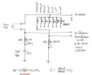
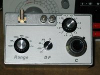
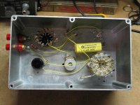
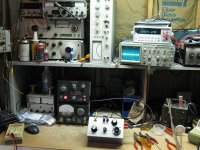
Conrad's Large Cap Bridge
For those interested in Conrad's cap bridge, here is some additional info for a version I recently completed. The bridge worked very well at the 60hz frequency Conrad designed it for, but I wanted to try it at the 120 hz specified by most data sheets. This however compressed the DF readout and as I couldn't find a log taper 250 ohm pot, Conrad suggested a 25 ohm pot be substituted which was calibrated to give a .1 DF max reading. An additional switch in the top right corner was added to sequentially add 13.263 ohm resistors for an additional .1 DF per step. A total DF range now is 1.2 at very good resolution on the low end where needed. Since I also have a GR1656 bridge which measures caps to 1100u, this bridge is used for large values.
For those interested in Conrad's cap bridge, here is some additional info for a version I recently completed. The bridge worked very well at the 60hz frequency Conrad designed it for, but I wanted to try it at the 120 hz specified by most data sheets. This however compressed the DF readout and as I couldn't find a log taper 250 ohm pot, Conrad suggested a 25 ohm pot be substituted which was calibrated to give a .1 DF max reading. An additional switch in the top right corner was added to sequentially add 13.263 ohm resistors for an additional .1 DF per step. A total DF range now is 1.2 at very good resolution on the low end where needed. Since I also have a GR1656 bridge which measures caps to 1100u, this bridge is used for large values.
Attachments
- Status
- Not open for further replies.
- Home
- Design & Build
- Parts
- How to test an old 60000uf cap ?