Hi all
I have an old Kenwood KR-55 receiver. It worked well until I decided to hook up a pair of 4 ohm speakers. No problem, but then I got carried away and cranked up the volume. Played for a while and then both channels went silent. I figure that I managed to cook the output transistors. Replacing them and/or anything else that got fried should be straight-forward.
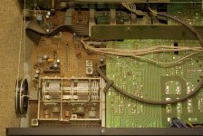
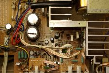
However, when I took off the top cover I was confronted by the mechanics of the tuner section. It's all beautifully made, with a long belt looped over various pulleys for the tuner needle et al. This is where I'm a little flustered. To get to the amplifier section all of this has to come off. How straight-forward is the re-assembly of these things?
I' ve been all over the internet to find a service manual, but most sites returned by the search engines seem to be constructed to lure us there with false promises. This is a phenomenon that is worth a discussion all of its own, but I digress. Other sites promises a manual but they want money for it. Being a tight-wad I'm very reluctant to hand out my card number.
Any general guidelines on taking apart analogue tuners (and putting them together again) would therefore be much appreciated. I can post a picture of the mechanics if that will help.
I have an old Kenwood KR-55 receiver. It worked well until I decided to hook up a pair of 4 ohm speakers. No problem, but then I got carried away and cranked up the volume. Played for a while and then both channels went silent. I figure that I managed to cook the output transistors. Replacing them and/or anything else that got fried should be straight-forward.
An externally hosted image should be here but it was not working when we last tested it.
However, when I took off the top cover I was confronted by the mechanics of the tuner section. It's all beautifully made, with a long belt looped over various pulleys for the tuner needle et al. This is where I'm a little flustered. To get to the amplifier section all of this has to come off. How straight-forward is the re-assembly of these things?
I' ve been all over the internet to find a service manual, but most sites returned by the search engines seem to be constructed to lure us there with false promises. This is a phenomenon that is worth a discussion all of its own, but I digress. Other sites promises a manual but they want money for it. Being a tight-wad I'm very reluctant to hand out my card number.
Any general guidelines on taking apart analogue tuners (and putting them together again) would therefore be much appreciated. I can post a picture of the mechanics if that will help.
see if the bottom panel doesn't screw off, manu older designs use an upside down PCB accesable from the bottom. The screws may be in or behind the feet.
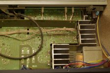
Taking off the bottom cover turned out to be straight-forward. Hat tip to digits.
I guess the best approach is to leave the PCB in place and just de-solder things where they are. A bit fiddly but dismantling all of this looks quite daunting.
I guess the best approach is to leave the PCB in place and just de-solder things where they are. A bit fiddly but dismantling all of this looks quite daunting.
Attachments
The Sanyo datasheet gives the 2SD613/2SB633 out as 85V, 6A, 15MHz devices. The fT of 15MHz seems hard to find in a TO220 high(ish) current device. Another datasheet from Wing Shing Computer Components Co., (H.K.)Ltd (WHO?) specs it as 8MHz.
About the closest match I've seen so far is the BD911/BD912. Same package and lead orientation (BCE) but 'only' 3MHz.
Matching of transistors? I will have to look into that.
About the closest match I've seen so far is the BD911/BD912. Same package and lead orientation (BCE) but 'only' 3MHz.
Matching of transistors? I will have to look into that.
Last edited:
did you check those fuses first?
replace them if blown and see if it's not just a case of blown fuse
replace them if blown and see if it's not just a case of blown fuse
The fuses are OK. Checked them with my trusty Fluke 77. As the old saying goes, they were protected by the transistors.
What about a pair of MJE15032/3 ? THe only problem is they are 30MHz and stability might be an issue.
The fuses are OK. Checked them with my trusty Fluke 77. As the old saying goes, they were protected by the transistors.
That makes no sense. The most common failure of power transistors is to melt and become a wire which then takes out the fuses as they also melt. It's time to get in there with a meter and find out what's going on.
I have on a couple of rare occasions seen fuses that did not appear 'blown' but were in fact open. Have you measured the fuses with a meter?
G²
The Sanyo
About the closest match I've seen so far is the BD911/BD912. Same package and lead orientation (BCE) but 'only' 3MHz.
.
BD911/912 should do it.
Ft at 1A is about 5mhz , the 3mHZ figure is at 0.5A and is a minimum value.
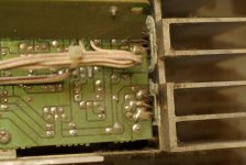
Also, the heatsinks are quite small , and even if this seems a low power
amp, they are unlikely to sustain the dissipated heat even at 8R ,
let alone at 4R , wich is why the transistors did blew..
Have you measured the fuses with a meter?
Yes. I pulled them out one by one and used the continuity/diode test function on one of these.

Thanks for the advice on replacement transistors. My local shop does not stock the MJE15032/3. I can get them from a wholesaler but only in a pack of 5. No hardship there though. The leftovers can go into my spares drawer.
The higher fT might pose a problem. From playing around in LTspice I know that popping a modern transistor into an old design could bring about unwanted results. I think I will try the BD911/2 first.
Last edited:
Yes. I pulled them out one by one and used the continuity/diode test function on one of these.
Fine meter but it still doesn't add up. The fuses are good and not blowing so I doubt your power transistors are bad. What I meant with the meter is to check the voltages on the fuses (both ends). I'm sure I'm making a mistake by assuming the fuses are in the power feeds (+ & -) to the amplifier assemblies but if that's the case I'd expect positive and negative Voltages on the fuses an consequently to the amplifiers. Do you think maybe one (or both) channels is putting out DC and going into 'protect' mode ?
G²
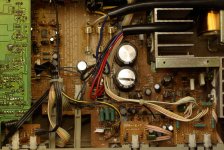
I haven't done much else in the line of measurements - only figured out how to get into the amp this afternoon. With the shops being closed, I've placed the repair on hold. At least one of the output trannies is gone from the looks of it (black scorch marks on the heatsink). They are quite cheap and with the originals being unavailable I will replace the lot, but I will check for other problems before turning the power back on.
The plan goes as follows - power on, check for DC. Power off, desolder output trannies. Check other components, replace where needed. Power up, check for DC again. Power off, put in new output devices. Power on, check for DC again. Apply test signal and oscilloscope and check some more. Then hook up eight ohm speaker. Haven't done much of this and the previous time was quite a while ago. Any comments are welcome.
The plan goes as follows - power on, check for DC. Power off, desolder output trannies. Check other components, replace where needed. Power up, check for DC again. Power off, put in new output devices. Power on, check for DC again. Apply test signal and oscilloscope and check some more. Then hook up eight ohm speaker. Haven't done much of this and the previous time was quite a while ago. Any comments are welcome.
Last edited:
- Status
- Not open for further replies.
- Home
- Amplifiers
- Solid State
- How to take apart an old Kenwood receiver?