Hello,
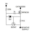
I'm not sure where to post this but hopefully should be simple to answer. I'm going to use this CCS on tube cathodes. It will be referenced to a negative supply since there isn't enough voltage from cathodes to ground. It also requires a positive supply to bias the zener and this will come from B+ since it's the only available. I have a couple of questions about this. First, do all these supplies need to be super clean? It would be handy to get them from early stage of filtering and there will be a few volts of ripple. I'm thinking that it should work but is it optimal? Especially for the B+ there is a very convenient point to tap at the heaters DC elevation, the usual voltage divider bypassed with a cap. Would this work? The second question is if there is any problem from that all these supplies are used in different stages of the amp and none on the tubes where the CCS is attached. All of them are referenced at the same ground though.
I'm not sure where to post this but hopefully should be simple to answer. I'm going to use this CCS on tube cathodes. It will be referenced to a negative supply since there isn't enough voltage from cathodes to ground. It also requires a positive supply to bias the zener and this will come from B+ since it's the only available. I have a couple of questions about this. First, do all these supplies need to be super clean? It would be handy to get them from early stage of filtering and there will be a few volts of ripple. I'm thinking that it should work but is it optimal? Especially for the B+ there is a very convenient point to tap at the heaters DC elevation, the usual voltage divider bypassed with a cap. Would this work? The second question is if there is any problem from that all these supplies are used in different stages of the amp and none on the tubes where the CCS is attached. All of them are referenced at the same ground though.
Attachments
Hi,
Very good web page, where you can get some really good info on CCS usage in tube circuits: tubecad.
Owner/author: John Broskie
Regards.
Very good web page, where you can get some really good info on CCS usage in tube circuits: tubecad.
Owner/author: John Broskie
Regards.
If you use a two-wire CCS, the + aux supply's quality issue disappears, and if the CCS is good enough, the quality of the - supply becomes irrelevant too.
Some ideas here:
Improved 2W current sources (II)
Some ideas here:
Improved 2W current sources (II)
Last edited:
🙂 I think I understand how Alice takes care of the dirty B+ for Bob! Dave looks like my schematic but Cathy is a bit different... I take it that B+ should be clean. I'll look for two wires CCS but it has to burn a few watts so it must include a power mosfet. Many thanks to all!
Zeners can generate _lots_ of noise, you always need a capacitor (or better RC filter) across them.
I've been searching on this. Any suggestions for a two terminal CCS capable for high voltage (>100V) and low current (<10mA)?
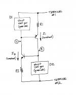
The standard approach to creating an only-2-terminals current source, is to build two CCS subcircuits. One for housekeeping/biasing, and the other to source/sink the majority of the required load. Bob Cordell's "ring of two" illustrates this nicely (2nd ed, Fig 2.14b). However, since you insist upon MOSFETs rather than BJTs, you'll probably want to include a 20 turn trimmer potentiometer in your version. That would be one easy way to deal with the rather large spread of Vgs_th voltages found on MOSFET datasheets.
Iout = I1 + I2 = constant1 + constant2 = constant current source
There's no requirement that R1==R2 or that Vref1==Vref2, so there's no requirement that I1==I2. The only thing you require is that the sum of I1 and I2 equals your desired constant current value.
You might want to install an optional "startup" mechanism, to prevent the circuit from latching in the stable state I1 = I2 = zero; Cordell shows a 22 megohm resistor from NPN collector to emitter. You might also want to install noise attenuating capacitors (or even RC lowpass filters) as others have mentioned. And then gate oxide protection zeners etc.
BEWARE: feedback regulated CCS circuits like this one, misbehave badly when the voltage across them falls too low. This can happen to an active plate load when the amplifier is driven into clipping, to name one example. So be sure to test the circuit thoroughly in the simulator and on the lab bench, before hooking it up to other expensive gear like loudspeakers. You wouldn't want a comatose CCS to hurt anything downstream. Including your ears.
_
Attachments
Last edited:
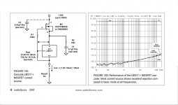
Thanks for replying! I have nothing against BJTs I just understand mosfets better. BTW, when I'm saying "my CCS" in post #1 I mean the one I posted, it's not my design. I.m not very good for that so I'm looking for something ready and tested. I will take in mind your suggestion but there is also another design that seems attractive. It can be found here https://audioxpress.com/assets/upload/files/Sources_101_P2.pdf-also attached. It works a charm for 40mA -tested but it's not suggested for lower than 10mA -not tested. I gather it's because of the LM317. Couldn't substitute this for a BJT?
Attachments
The logical choice would be a depletion MOS-based CCS, very much like the jFET type, except NMOS are available for high-power and voltage.I've been searching on this. Any suggestions for a two terminal CCS capable for high voltage (>100V) and low current (<10mA)?
Something like the DN2540 or similar, from Supertex and others.
Otherwise, the examples I gave, both the in the first and second thread, are suitable with transistors like MJE340/50, MPSA42/92, 2N5401/5501.
Edit: don't throw a 317 into a DN2540 CCS: it will bring deterministic adjustability, but other than that it is crap.
Use a cascode for high performance, but stay with pure NMOS, and adjust the current with a variable resistor, or better a selected fixed resistor.
I am sure there are suitable examples in the tubes forum
Last edited:
I had a small break and now back online.
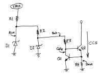
Elvee, I reattach your schematics from the other thread linked in post #3. Since I'm going to use the CCS at the cathodes of a differential pair with a negative supply of around 100V I expect not to have problems at cold start up or clipping so the first scheme to the left should be OK to start, shouldn't it? And if it's set for 7mA then the 2N4501 seems fine, or should be replaced with MJE350? I happen to have BD140 btw.
Elvee, I reattach your schematics from the other thread linked in post #3. Since I'm going to use the CCS at the cathodes of a differential pair with a negative supply of around 100V I expect not to have problems at cold start up or clipping so the first scheme to the left should be OK to start, shouldn't it? And if it's set for 7mA then the 2N4501 seems fine, or should be replaced with MJE350? I happen to have BD140 btw.
Attachments
Connecting one of these capacitors across each pair of 1N4148's, might provide an inexpensive improvement. The capacitors operate at a working voltage less than 1.6 volts.
option 1: . . . . 80-ESK108M6R3AG3AA
option 2: . . . . 598-338CKS010M
option 3: . . . . 80-ESK688M010AM2AA
option 1: . . . . 80-ESK108M6R3AG3AA
option 2: . . . . 598-338CKS010M
option 3: . . . . 80-ESK688M010AM2AA
Or use green LEDs like your suggestion? And then the two resistors adjusted according Vbe? Can I use BD139/40?
There are no free lunch ... if you want to use LEDs as reference, must to drive its with current.
Instead of BJTs use cascoded depletion FET CCS.
Instead of BJTs use cascoded depletion FET CCS.
Every time I tested the circuit in the real world, it self-started, but circuits can be vexing, and I would include the 22meg resistor as a precaution (could be 33 or 68meg, value doesn't matter)Elvee, I reattach your schematics from the other thread linked in post #3. Since I'm going to use the CCS at the cathodes of a differential pair with a negative supply of around 100V I expect not to have problems at cold start up or clipping so the first scheme to the left should be OK to start, shouldn't it?
If you expect a permanent 100V across the CCS, the dissipation will be 350mW, which is OK for a 2N5401.And if it's set for 7mA then the 2N4501 seems fine, or should be replaced with MJE350? I happen to have BD140 btw.
The BD140 has a Vce of only 80V, thus for 100V it is (in theory) insufficient.
A green LED is OK, and will give a first order temperature compensation.Or use green LEDs like your suggestion? And then the two resistors adjusted according Vbe? Can I use BD139/40?
Recalculate the current-setting resistors for ~=1V across each. Beware of super-green LEDs having a Vf of 3V.
Adding parallel capacitors as Mark suggested will increase the AC impedance, if it is required
- Home
- Amplifiers
- Power Supplies
- How to supply a CCS