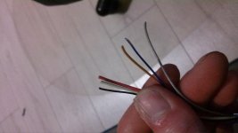
My Creative 9 pin male din is damaged. I want to solder cable directly to PCB. I have 6 small cables: red,blue,gray,white,orange,black.
An externally hosted image should be here but it was not working when we last tested it.
Check the wiring to find out after seeing if it is a standard pin out.
Image not opening, try uploading again.
Image not opening, try uploading again.
Creative Labs Inspire A200 Speaker System
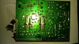
PCB MODEL NUMBER:553N8251
Socket name:MD-90SM
Jack which from I cut the cable MD-90
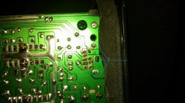
In picture below I marked 1-9 no. in red square, these are the spots from D9 pin socket, I assume that I need to solder these six cables somewhere there.
six wires: white,gray,blue,red,brown +black (probably ground)
where to solder them? I need to make sure that they will be well soldered.
if someone can mark the places of soldering on the enclosed picture - I WILL BE GRATEFUL
PCB MODEL NUMBER:553N8251
Socket name:MD-90SM
Jack which from I cut the cable MD-90
In picture below I marked 1-9 no. in red square, these are the spots from D9 pin socket, I assume that I need to solder these six cables somewhere there.
six wires: white,gray,blue,red,brown +black (probably ground)
where to solder them? I need to make sure that they will be well soldered.
if someone can mark the places of soldering on the enclosed picture - I WILL BE GRATEFUL
Attachments

Last edited:
Didn't you take notes or a picture before cutting the wire?
Guessing is impossible.
Ask Creative themselves.
Guessing is impossible.
Ask Creative themselves.
Perhaps this helps:
هندسة الالكترونيات : A creative speaker SBS A200
a200.jpg (hosted by elektroda.pl) Hope You speak Polish
هندسة الالكترونيات : A creative speaker SBS A200
a200.jpg (hosted by elektroda.pl) Hope You speak Polish
Last edited: