Hello folks, I am trying to repair my Citation 7.1 Amplifier (Rev. C). I do have the service manual but I do not see anything about how to properly set the Bias. It does have a Bias trim pot. Is anyone familiar with this amp that can possibly help me with this task? Thank you!
CC output stage => 20-30 mV across each emitter resistor
CE output stage => about 50-60 mV across each emitter resistor
Anything more than that... the distortions will actually increase & you'll be wasting the power as heat - virtually!!
Anything lower than that - you'll see the crossover distortions on the scope... but you won't be able to hear it...
CE output stage => about 50-60 mV across each emitter resistor
Anything more than that... the distortions will actually increase & you'll be wasting the power as heat - virtually!!
Anything lower than that - you'll see the crossover distortions on the scope... but you won't be able to hear it...
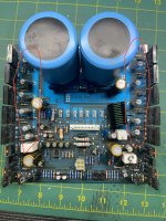
Hello Extreme_Boky, Thank you for helping out. I am not quite sure how you mean I need to do this. I do not have any fancy equipment or a scope. I just have a Fluke 87v that I think will work to measure mV. The issue I am having is one of the modules gets quite warm after a while. Much warmer than the rest. I have had this issue before with a different module and I sent it off and it turned out that the bias was set too high. This time I would like to learn how to set it myself. With the help of kind folks like yourself, I think I can do it. Please assist me if you don't mind. I have included some photos of the module with what I think are the resistors you are talking about are circled. Can you please explain to me how to do this? I have also included a second photo that's not marked up so feel free to mark it up for explanation purposes. Thanks a million!!
Attachments

Last edited:
If you are unsure and if we can not see the manual then I would suggest you measure the voltage across a few of those resistors you have circled in the other cooler running modules. If they are reasonably similar to each other (they should be) then note the average voltage and set the bias on your hot module to similar.
Be very very careful. One slip and it all goes bang.
Be very very careful. One slip and it all goes bang.
Thank you Mooly, Roger that on the slip. I will be extremely careful. When you say across the resistors, you mean from one leg to the other correct? Just want to make sure my understanding of the terminology is correct. Also, should this be done while I'm actually playing music or something through it or just simply powered on? I did notice it gets warm even when no speaker is connected to it so I assume just test with it powered on?
Also, would it be wise to set my meter to volts DC to start or should I set it directly to mV?
Also, would it be wise to set my meter to volts DC to start or should I set it directly to mV?
One leg to the other. No music and preferably no speakers attached. Good practice is always to start on a higher volt range if unsure. Just be careful not to slip with the probes.
Just to be clear on that, it is measuring across individual resistors, not from one resistor to another.When you say across the resistors, you mean from one leg to the other correct?
Gotcha, yes I will start at a higher voltage setting. Thank you for that advice. Also I have some fine test leads that I thought to clamp on one end of the resistor and for the other end I have some 3”long needle piercing attachments that are insulated. Now I just have to practice on not shaking. Lol
These look easy to get to.
Are you sure the manual doesn't detail how to do this. I see that central plug marked 'Test' which may have the recommended test points to do this, and the recommended value.

Are you sure the manual doesn't detail how to do this. I see that central plug marked 'Test' which may have the recommended test points to do this, and the recommended value.
May I ask what probably is a dumb question? These resistors are silk screened “5 Watt” on the board. Why such a high wattage resistor if we are only talking mV? Is it because of the current is high?
Thanks, interesting. I can't just see any procedure either.
The 0.33 ohm resistors suggest a bias point of around 24 millivolts across each resistor but the recommended figure may be lower than that because of heat dissipation which is why I recommend you check the other 'good' modules first and see what they are set to.
They are rated at 5 watts because they see very high peak currents when the music is loud and the speaker load impedance is low. When idling they see only the bias current flowing.
The 0.33 ohm resistors suggest a bias point of around 24 millivolts across each resistor but the recommended figure may be lower than that because of heat dissipation which is why I recommend you check the other 'good' modules first and see what they are set to.
May I ask what probably is a dumb question? These resistors are silk screened “5 Watt” on the board. Why such a high wattage resistor if we are only talking mV? Is it because of the current is high?
They are rated at 5 watts because they see very high peak currents when the music is loud and the speaker load impedance is low. When idling they see only the bias current flowing.
ahhh. Makes total sense and that’s why you suggested I should test without speakers connected. Thank you. I will probably attempt this later today or tonight. Waiting in a fine point sikver marker so I can pit a small dot on the pot to mark the current setting just in case
The reason I always say to test without speakers is two fold. Firstly if they are not connected then they are safe... just in case you did short anything. Secondly if they there is any significant DC offset then that will cause a small current to flow in the speaker (which is fine) but that current skews the result you measure across the resistor. One set of resistors would show an increase in voltage and the other set a decrease.
Looking at the circuit at that last point should not apply to this amp as the opamp is configured as a DC servo to maintain a true zero volts DC offset.
Looking at the circuit at that last point should not apply to this amp as the opamp is configured as a DC servo to maintain a true zero volts DC offset.
Hello Mooly, you are the man!! I think I got success and fortunately no slips. Here is what I did, first I measured across the resistors. Actually I just chose one resistor consistently on all the modules since there is only one trim pot. I first measured the hot module and got approximately 15mV. Then I measured the others and got between 0 and 4.9mV. I was not sure which is the correct value so I opened up my other amp (same version) and measured those. There I got .2mV, 0mV, 0mV, .1mV. Seemed pretty close to me so I remembered one of these modules was sent back to the creator to set the bias. This one was the one measuring .2mV. So I just set all to .2mV on the project amp. I have it playing now and it does not seem to be getting warm anymore. I did crank up the volume and it sounded pretty good to my ears. I'm sure some fancy equipment can measure distortion and maybe find that it could be optimized more but for now I am pretty happy playing it safe. This amp is a nightmare to work on. This whole ordeal started when I recapped it. Just about all the caps were bad after 28 years. I have 3 of these amps. I recapped one (revision B) with no issues whatsoever. However this one shorted a bunch of transistors on each one of the modules. Not sure why since the other was fine. Only thing I can think of is I used an 8ohm resistor to discharge the big capacitors and this revision did not like that. Or maybe I shorted the heat sinks of a couple transistors together while removing the metal heat sink clamps before discharging capacitors. I remember I did get some sparks doing this so I don't know. Anyhow I have learned my lesson and started discharging using a 1kohm resistor and discharging via the wire terminals before removing the clamps as to avoid any mishaps.
👍 excellent.
Firstly it is normal for the voltage to wander a bit as the transistors heat up.
If you look at the circuit you will see 5 pairs of output transistors per channel. All the transistors in theory should equally share the current... give or take. If you measured 15mv then the current would 0.015/33 which is 45 milliamps. That is per transistor if they share equally. The supply to outputs is -/+60 volts and so you have 60*0.045 = 2.7 watts per transistor. Ten transistors is 27 watts dissipation just for one channel... which is lot really. And that is just one channel.
For cool running and reliability lower is better.
It would be interesting to know what the recommended current is but I think running it low is going to be safer.
Well done 🙂
I agree with you 100%. At this point I want to play it safe. Mooly I want to thank you from the bottom of my heart. Without your help this would not have been possible and I would have continued my sleepless nights of tinkering and blowing sh%t up....lol
I still have a module down due to a blown transistor but my Digikey order should be here by Friday and I hope to get this amp closed up and put back in service by this weekend. I sure learned a lot from this experience. Mainly I learned to be more cautious and play it extremely safe even if it's taking a few more minutes to take necessary precautions when dealing with high voltage/current caps. I wish I knew what caused this mess in the first place as the first amp went perfectly smooth.
Thank you again Mooly, you are the best!! Also, I love, love, this site/forum. Unlike some other sites, people here seem to be very helpful and courteous. I have had my butt chewed out before on other sites just by asking a simple question. None of that here thank goodness.
If you only have a digital meter, the safe way to set the bias is to measure the voltage across the bias spreader circuit. I know this because I designed and manufactured these amplifiers for Harman International. We set the bias/idling current using one of our Audio Precisions using the THD analyzer at 20KHz.
You can measure the voltage across C12, a 0.047mfd blue coloured capacitor. Set the trimmer for 3.35v, no more with NO load. Let the amplifier idle for about 30 minutes and recheck this voltage
If it is easier to probe, measure between the bases of Q28 and Q29, OR from Q22 collector to Q25 collector. Be carefull with the probes.
The method of setting the bias by measuring across emitter resistors has nver been a safe way for me. Idling each power device at 40-50mA will cause the sink to get quite hot.
Steve Mantz
Zed Audio Corporation
Thank you Steve. Doing that now. However when I took the reading across c12 before readjusting the pot again, it was pretty close to your suggestion. It was at 3.29v. I just bumped it up a bit to 3.35v (which was not easy since it had to be the slightest nudge) and waiting the 30 min. By the way, These amps have run trouble free since I purchased them new in 1995. The serial numbers are under 200. Well done sir. Great amps!
By the way, I own 3 and my brother owns 3. Neither of us have had any issues other than capacitors after 28 years.
By the way, I own 3 and my brother owns 3. Neither of us have had any issues other than capacitors after 28 years.
- Home
- Amplifiers
- Solid State
- How to set BIAS on Harman Kardon 7.1 amplifier?