the one responsible for the coloration of the sound
is the resistance of feedback in the amplifier 😛
the best solution is to inject the signal directly with a capacitor
as happens in the current / voltage converters 🙂
is important to use components with a low gain
especially with low supply voltages 🙄
is the resistance of feedback in the amplifier 😛
the best solution is to inject the signal directly with a capacitor
as happens in the current / voltage converters 🙂
is important to use components with a low gain
especially with low supply voltages 🙄
Attachments
No, sorry, I haven't got a clue what you are saying. Resistance in the feedback network causes problems which can be solved by using an input coupling capacitor? Components with low gain? Most components have no gain, as they are passive.
indeed youve lost me too, inject the signal directly with a capacitor as happens in IV convertors? thats normally done with a resistance, unless you mean in a voltage out dac like most I see you playing with, which makes it a buffer, or voltage gain stage, not an IV stage, if you avoid the resistor in an IV convertor, the resistance is simply supplied by the next stage input impedance/resistance, which is not as linear as a resistor. you have not removed it at all, just shifted it to a less ideal position
Congratulations, you have built an inverting amplifier.
Voltage gain is now set by R1 and the output impedance of the previous stage.
Inverting operation circumvents several distortion mechanisms potentially present in noninverting amplifiers, as discussed e.g. in Samuel Groner's opamp measurements. Hence it is not uncommonly preferred in power buffers.
I'm afraid this isn't anything new, groundbreaking or spectacular though...
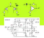
with R1 = 27K (1mA with 1K develops 1V) is obtained, however, an open-loop gain
is a new idea to use this condition in a power amplifier as it were a zero-feedback ideal architecture
direct entry (C1) puts R1 in a role of DC servo
and generates an effect presence unpublished
is a new idea to use this condition in a power amplifier as it were a zero-feedback ideal architecture
direct entry (C1) puts R1 in a role of DC servo
and generates an effect presence unpublished
Attachments
No, I still don't get it. Describing a DC blocking input coupler and a feedback resistor as together forming a DC servo, if that is what you are saying, is the sort of nonsense that ad writers write. And feedback is now 'a zero-feedback ideal architecture'?
If the set ratio of income exceeds the maximum possible
system works as an open loop gain
but this is not the important aspect
what is interesting is that it sounds really good 🙂🙂🙂
system works as an open loop gain
but this is not the important aspect
what is interesting is that it sounds really good 🙂🙂🙂
- Status
- Not open for further replies.
- Home
- Amplifiers
- Solid State
- how to remove stains in your AMP