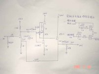
I search about method to reduce gain of this Preamp (They're called CAT SL1 ?) 12AU7 plate load + 12AX7 mu stage + 6DJ8 cathode follower.
When I built this preamp it has a lot of gain and hum on the output, gain of this preamp = 20K/1K = 20dB ?
When I connected to osciloscope its responsibled curve is flat only 40Hz - 12KHz
Regard
analog guy
When I built this preamp it has a lot of gain and hum on the output, gain of this preamp = 20K/1K = 20dB ?
When I connected to osciloscope its responsibled curve is flat only 40Hz - 12KHz
Regard
analog guy
Attachments
I would think the gain is closer to 26db!
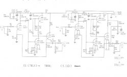
I would scrap it and build the Aikido instead. You have all you need to build it and it will reduce gain to about 18db.
I would scrap it and build the Aikido instead. You have all you need to build it and it will reduce gain to about 18db.
One way is to decrease the value of the 20k feedback resistor from the cathode of the CF back to the input stage, but then you probably have to recalculate the working point for the input stage.
Another strange thing: The grid of the lower 12AX7 in the mu-follower is floating; you should connect the grid to ground via a resistor.
Jan E Veiset
NO-6600
Another strange thing: The grid of the lower 12AX7 in the mu-follower is floating; you should connect the grid to ground via a resistor.
Jan E Veiset
NO-6600
If you want to maintain the original schematic , you can put a 20K resistor in series with a electrolytic capacitor, in parallel the original 20K feedback resistor.
That way you cut the gain in half.
Originally you have 21X and with the mode 11X...
That way you cut the gain in half.
Originally you have 21X and with the mode 11X...
Oh dear. Mu follower with an AX7 in a preamp, why all this gain? Bottom AX7 has a floating gate (probably a drawing error. Also the cathode load of the output stage shares function with feedback network and influences input bias. All in all, I think one could do a better preamp with half of the same parts!
Yes, it's a really SL1 cloned schematic but I don't know why they're design in this way.
Maximum output is 50V !!! sound not clear, not smooth, less airy, too sensitively with hum !?!
Please comment in my newer idea : change Rp of 12AU7 to 150K to decrease gain and current, add Rg 1K and 475K to ground for bottom 12AX7, decrease 6DJ8 output capacitor from 10uF to 4.7uF but why they used only 47K for output impedance ?
I still confuse for this schematic if anybody had modified them please tell me for your modification
Thanks for advance
analog guy
Attachments
- Status
- Not open for further replies.