Folks:
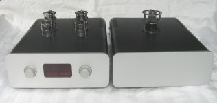
About 15 years ago, Bas Horneman hosted a couple of group buys for Aikido preamplifier pcbs (as I recall, this was before John Broskie began selling boards). I built a noval Aikido using Bas's boards and have been very satisfied with that project until very recently, when a few component changes were made to my tube system. The problem now is that the gain is too high, perhaps by 6 - 10 dB.
I'm no expert in tube topologies and have no clue as to how to reduce the gain on my Aikido. For me, the ideal solution will be as simple as possible and will not degrade the sonics of this preamp.
In my Aikido, T1 are 6N1P and T2 are 6H30. Would swapping or replacing the tubes be a solution?
Your advice is greatly appreciated!
Regards,
Scott
Attachments
A resistor 100k in series with the input woul dbe the simplest solution.
Changing cathode follower won't change gain. Changing the first tube would do a very minimal change.
Changing cathode follower won't change gain. Changing the first tube would do a very minimal change.
No, i suggest 100 k between input connector and the pot. This saves the grid stopper on the first tube and in addition increases the input impedance to 150k.Like this ?~+10dB gain.
Mona
What source is driving the Akido line stage, and can it drive 10k, or 100k?
The only proper solution is an input attenuator. Don't add global nfb to lower the gain.
The only proper solution is an input attenuator. Don't add global nfb to lower the gain.
No, i suggest 100 k between input connector and the pot.
Turning down the volume is not a reduction in stage gain😀
rayma:
The primary source is a music server; the DAC is a Schiit Modi Multibit. The system also includes a Jolida JD100 CD player and Jolida JD402 tuner.
Regards,
Scott
The primary source is a music server; the DAC is a Schiit Modi Multibit. The system also includes a Jolida JD100 CD player and Jolida JD402 tuner.
Regards,
Scott
Would swapping or replacing the tubes be a solution?
How about reading the original article before you go any further? From Broskie's article:
Since the circuit's gain is equal to one half of the mu of the first tube, the gain could be easily altered by altering the tube used in this position. Thus, a 12AU7 would yield a gain of 8.5 (18.5dB); a 12FQ7, 10 (20dB), a 12AT7, 30 (29.5dB).
New Tube Circuit: The Aikido Amplifier
Changing the first tube would do a very minimal change.
Mr. Broskie, the designer of this circuit, disagrees with you. See my post above. If you do a quick sim you can convince yourself that he is correct.
At the input, a series 10k, followed by a shunt 10k, would give -6dB attenuation.
Then you wouldn't have to change resistors on the board in order to use different tubes.
Then you wouldn't have to change resistors on the board in order to use different tubes.
Yes change the first tube.
The original 6N1P has a amplification factor of 35 a 12AU7 has a amplification factor of 17 or so.
The first stage amplifier was designed back in the 1940's or earlier not by John Broskie.
The original 6N1P has a amplification factor of 35 a 12AU7 has a amplification factor of 17 or so.
The first stage amplifier was designed back in the 1940's or earlier not by John Broskie.
DualTriode:
Okay, I'm a little confused by your post. Are you saying a 12AU7 can be swapped in for a 6N1P? The former's heater voltage is half that of the latter.
Regards,
Scott
Okay, I'm a little confused by your post. Are you saying a 12AU7 can be swapped in for a 6N1P? The former's heater voltage is half that of the latter.
Regards,
Scott
The 12AU7 filaments can be wired in parallel to use 6.3V, but its pin 9 is then the other end
of the filament. The 61NP uses pin 9 for an internal shield that should be grounded.
So some rewiring would have to be done.
The mu/2 first stage is described in the Vacuum Tube Amplifiers volume of the MIT Radiation Lab
series published after WWII (see p. 464), but Broskie added hum cancellation, which is why he
calls it Akido, as he does with other, different circuits to which he also adds hum cancellation.
http://www.nj7p.org/Manuals/PDFs/Books/MIT-Radiation-Lab-Series-V18-Radar-Engineering.pdf
Last edited:
0.33petertub:
Roughly how much of a reduction would the 100k resistor provide?
Regards,
Scott
150/50
Or as ontariomaximus writes : 10dB
Go for the 6CG7 in the first spot, it's the same pinout as the 6N1P, so it will be an easier change than using a 12AU7, and should be lower distortion too.
On the Broskie Aikido PCB, you can't use a 12.6V heater tube type with a 6.3V heater tube type at the same time (like a 12AU7 with a 6N30P). That means you want to choose a 6.3V heater twin-triode, not a 12AU7 (or similar 12.6V heater tube).
In addition to 6CG7/6FQ7, you could also try 6GU7 in place of the 6N1P. All have the same pinout and the same heater requirements. In other words, pin-compatible.
6N1P: mu = 33, heater = 6.3V 0.6A
6CG7/6FQ7: mu = 20, heater = 6.3V 0.6A
6GU7: mu = 17, heater = 6.3V 0.6A
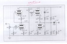
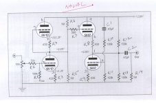
If you could supply us with a schematic of your particular build, we could figure out which of the above types would be possible to swap in without changing any resistor values.
Since the mu of the 6N1P is 33, and the mu of the 6GU7 is 17 (about half), simply swapping a 6GU7 into the first tube socket should reduce the gain by 6dB, which is what you estimate you need. That's pretty easy, but it would be nice to know what values of cathode resistors you have installed in your board, just to be safe.
--
In addition to 6CG7/6FQ7, you could also try 6GU7 in place of the 6N1P. All have the same pinout and the same heater requirements. In other words, pin-compatible.
6N1P: mu = 33, heater = 6.3V 0.6A
6CG7/6FQ7: mu = 20, heater = 6.3V 0.6A
6GU7: mu = 17, heater = 6.3V 0.6A
If you could supply us with a schematic of your particular build, we could figure out which of the above types would be possible to swap in without changing any resistor values.
Since the mu of the 6N1P is 33, and the mu of the 6GU7 is 17 (about half), simply swapping a 6GU7 into the first tube socket should reduce the gain by 6dB, which is what you estimate you need. That's pretty easy, but it would be nice to know what values of cathode resistors you have installed in your board, just to be safe.
--
Last edited:
- Home
- Amplifiers
- Tubes / Valves
- How To Reduce An Aikido's Gain?