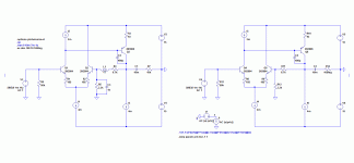
I'm trying to plot the open-loop gain of a single-transistor-input circuit in SPICE, without using a loop-gain probe or similar. To explain it better, I've shown what I want to do in the first two attached pictures, but for a diff-pair input. In the left diff-pair circuit, I've set it up to run open loop using a large inductor and capacitor in the feedback network. The open-loop gain is 72dB (Q3 current gain = 165) and gain-bandwidth is 1MHz (blue line on the graph). The right-hand diff-pair circuit is operating with feedback but I can still plot the open-loop gain as output divided by differential input voltage (green line, identical to blue line).
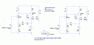
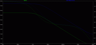
I want to do the same thing for a single-transistor-input circuit. The third attachment shows the circuit. Again, I have the left circuit operating open-loop and it has 55dB open-loop gain (Q2 current gain = 210) and 1MHz gain-bandwidth (green line on the graph). However, for this case, I can't work out how to plot the open-loop gain while the feedback is activated (i.e. right-hand circuit). The blue line on the graph is output voltage divided by v.be(Q3), but this doesn't give the open-loop gain.
So, any hints on how to plot the open-loop gain for this case? Or what the differential/error voltage is defined as for the single-transistor case?


