I actually found a potential issue (maybe not THE problem, but A problem). The i2s clock signal coming to my DSP looks pretty nasty. There are a number of ways to clean it up, and I have them at hand, its just a matter of trial and error there.
But, I have reconfigured my DSP to take the analog input and use the internal clock, so I will run my THD stuff with analog and see where we get.
I would likely have to remove the inductor to do this measurement? There are quite a few recommended replacement parts to "tune up" these amps by various folks on the forums here. TPA3116D2 Boards
If I'm going to the trouble to take off the (generic questionable quality) inductors, I might as well just buy the recommended name brand replacements and put them there. I'm expecting the SMD inductors not to want to come off willingly 🙂
I actually recognize some of the parts from my $$$$ Class D amp in my car. I don't think i need that level of quality here, but it is nice to know that some of that stuff makes a difference.
First of all: Do not operate your amp without inductors!
And swapping the chokes you should know: Same shapes & sizes are often delivered by a multitude of brands.
Whereas the difference between brands most of the time is minor.
If you want improve your chokes, chose bigger ones - no matter which brand.
More massive cores result in less flux swing and yield better linearity.
So the chokes on your pcb do not look that impressive.
To desolder I normally use two soldering irons heating both pads simultaneously.
Some pre-heat from the bottom (if available) may help as well.
Last edited:
Interesting! What is it, safety belts?😉I actually recognize some of the parts from my $$$$ Class D amp in my car.
oops, I may have misspoken, i meant test the inductors without the board, not the board without the inductors 🙂
I have access to a hot air station, i just didn't want to go through the trouble just to measure the inductors. I have another Digikey order in the making, so maybe I'll add inductors and better caps to the order and use them if I need them.
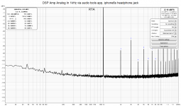
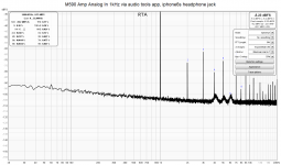
I finally have some thd spectra! They look surprisingly similar in the high end, but the low frequencies are different.
The DSP amp is the Dayton/sure/wondom 2x50 amp with the ADAU1701 DSP integrated.
The M590 is the TPA3116 amp favored by TPA3116 guru FauxFrench. It has most or all of the mods that people do already in it. Nice baseline.
As a trained spectroscopist (chemical), I'm familiar with FFT data, but I'm not sure what i should be looking at here for diagnostic purposes. The dsp amp certainly has a much lower noise floor. I had previously attributed it to the digital audio pipeline, but maybe the amp is just really clean.
What do y'all think?
I'm going to put the 2.1 crossover DSP program back on the amp and listen to it with the rest of the system. Perhaps there was something stupid happening with the i2s transport that caused distortion?
I have access to a hot air station, i just didn't want to go through the trouble just to measure the inductors. I have another Digikey order in the making, so maybe I'll add inductors and better caps to the order and use them if I need them.
I finally have some thd spectra! They look surprisingly similar in the high end, but the low frequencies are different.
The DSP amp is the Dayton/sure/wondom 2x50 amp with the ADAU1701 DSP integrated.
The M590 is the TPA3116 amp favored by TPA3116 guru FauxFrench. It has most or all of the mods that people do already in it. Nice baseline.
As a trained spectroscopist (chemical), I'm familiar with FFT data, but I'm not sure what i should be looking at here for diagnostic purposes. The dsp amp certainly has a much lower noise floor. I had previously attributed it to the digital audio pipeline, but maybe the amp is just really clean.
What do y'all think?
I'm going to put the 2.1 crossover DSP program back on the amp and listen to it with the rest of the system. Perhaps there was something stupid happening with the i2s transport that caused distortion?
Attachments
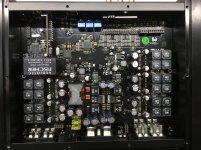
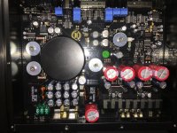
My Helix (‘discount’ brand of Brax ) car amps P Six DSP MK2 and P Two (with digital input board) have dsp and toslink data transfer to keep them quiet (my car’s head unit has fiber optic MOST, so i can go digital/fiber from the ipod/usb all the way to the amp.
I recognize the wurth inductors from the tpa3116 mods page. 🙂
I recognize the wurth inductors from the tpa3116 mods page. 🙂
Attachments
@Brianthechemist - thank you for posting the link to that TI app note.
In it they talk about "inductor linearity" and its effect on amplifier THD. This is a measurement you can actually make, if you have a spare N channel FET, a 10 mOhm resistor, a good function generator along with your oscilloscope.
We used a bazillion dollar Wayne-Kerr apparatus to do this, which was discovered to have insufficient capability for the inductor we were interested in, after we purchased the thing.
The basic circuit starts with a very well decoupled voltage source, usually lots of capacitance on the test fixture etch itself. One end of the inductor connects to this. The other end to the N-channel FET Drain. The FET Source connects to the 10 mOhm, through that component to ground. Drive the FET gate directly from the function generator, with a 50 Ohm terminating resistor. Use the scope to watch the signal across the 10 mOhm.
The idea is to slam the inductor to ground through the FET, using a pulse. When electronically grounded by the FET, current will rise linearly in the inductor - up to a point. You can start with a small pulse width and increase it, until the linear curve starts to bend - up - which is where the inductor is starting to saturate.
Of course, you have to be a little careful operating this, because when the inductor saturates, the FET takes a good beating, with only the 10 mOhm taking current against the FETs "on resistance".
If your function generator can do bursts, like, down to a single cycle, an enormous current can be generated with surprisingly small FETs. One guy was getting hundreds of amps from a FET that would fit on the end of a pencil eraser - single shot, repetitive at a few Hz. 20A should be no problem.
It's interesting that this performance aspect of an inductor effects amplifier THD in the critically audible 1 - 6kHz range.
Here’s another interesting app note on capacitor selection for input caps. https://pdfserv.maximintegrated.com/en/an/AN4333.pdf
Apparently the ‘inverse piezoelectric effect’ is dominant and responsible for the poor performance of the ceramic caps. Their capacitance changes with applied ac and dc voltage, thereby changing the gain on the signal that they are transmitting and degrading quality. There is one very telling plot where there is a plastic film cap that has a nearly linear response in relation to the relative nasties seen in the ceramics.
Always learning....
Last edited:
Ok, maybe the MLCCs should stay in computer MBs and such - and are a low hanging fruit for digital audio improvement - either by design or modification.
I bet there are some who pull of all the MLCCs from their PC MBs and replace them with plastic film caps.
Regarding the inductors, isnt their value determined by manufacturing costs? That is, you want to specify the cheapest inductor possible, so the smallest value you can get away with.
No limit on this in the DIY realm? Gigantic air-cores if you want - as long as you can physically connect them?
I’ve been looking at the inductors and I think I understand why the cheap boards have such high values. The quality ones have a flatter derating curve as you increase current. So I’m guessing that by overspec-ing cheap ones it is still cheaper than quality ones with the right inductance but less current sensitivity.
I just ended up buying quality inductors and film caps. Seems like i’m just buying headroom, but thats fine. Honestly, the work to measure if it is ‘good enough’ is more than the effort to replace the non ‘best practices’ components.
It pains the engineer and scientist in me, but the project manager in me looks at the effort, cost, and time. Haha
So you measured the footprints and ordered different values that might be better or you ordered parts that do not fit your pcb's and subjectively it will be high end quality once you destroyed the ampboards ? 😀
It pains the engineer and scientist in me, but the project manager in me looks at the effort, cost, and time. Haha
Hey, then you are a rare bird here😀
So you measured the footprints and ordered different values that might be better or you ordered parts that do not fit your pcb's and subjectively it will be high end quality once you destroyed the ampboards ? 😀
I'm quite OCD actually. 🙂 Definitely the first. My expectations are low, but to me these things were low-hanging fruit once I finally figured out the output filter design. After all, these are $40 amp boards, making a "perfect" TPA3116 board is like having the worlds fastest honda civic......
Replacements of the 0805 input caps and 10x10 inductors are drop-in. I only intend to replace the .68uF LC reconstruction filter caps. I didn't see why it was critical for the EMI snubber caps to be film. I found lands within existing footprints to solder the leads to without it looking like a moped in an Indian freeway carrying an entire family of 12 🙂
Overall, not much surgery.
Hey, then you are a rare bird here😀
That is literally my job actually. PM of hardware/software/scientific projects. That's why i KINDA know a bunch of stuff. I know enough to be a BS detector, but not enough to really do it all myself. Gets me in trouble when there isn't someone/something to refer to when something doesn't go as planned..
Any good references on how to interpret a THD plot?
- Home
- Amplifiers
- Class D
- How to objectively decide to upgrade caps? TPA3116