There is a simple method using Ltspice to measure the degree of
affectation of our circuit to the presence of capacitances,
thanks to ideal voltage sources, measure the zero crossing time,
we place a capacitor and we measure again, for a simple calculation
this gives the delay per pf of capacitance,
in this way we can evaluate the importance of capacitances in that node. In the scheme that I show you, you can play with different values
and measure the delay, the rest is a matter of calculation.
Obviously if the capacitances are not constant and associated to voltage,
neither is the delay of the passage of our complex signal through that level ...
And yea I Know , another nonsense for experts in this forum ....
that is the idea.
Attachments
Last edited:
It’s a bit weird to use the term jitter for amps, though I think I understand it more or less.
You wrote the following somewhere: "But what if this delay is not constant? How big does it have to be for us to perceive it? We are talking about the biggest problems of audio amplification." if I understand correctly you are not talking about how much the delay of 20 kHz sine wave compared to 20 Hz, but delay of a given frequency depending on VBE of transistor. This is probably due to the issue of charging and discharging the transistor? What do you mean by that term "precision of charging and discharging"? Please clarify this in more detail.
You wrote the following somewhere: "But what if this delay is not constant? How big does it have to be for us to perceive it? We are talking about the biggest problems of audio amplification." if I understand correctly you are not talking about how much the delay of 20 kHz sine wave compared to 20 Hz, but delay of a given frequency depending on VBE of transistor. This is probably due to the issue of charging and discharging the transistor? What do you mean by that term "precision of charging and discharging"? Please clarify this in more detail.
The delay in this case does not depend on the frequency,if I understand correctly you are not talking about how much the delay of 20 kHz sine wave compared to 20 Hz, but delay of a given frequency depending on VBE of transistor.
but on the level of the signal, due to variable capacitances
with the voltage, although within the circuit depending on its design
there are situations that can also cause this ,like capacitances in
non linear voltages (vbe) .
PE A signal , from 1 to 2v , has different delay that 2 to 3 v
Last edited:
Yes. That's exactly what I mean. It is a possible way to minimize the time/phase error (and dependency the capacitance change from VBE change) is the "current drive" principle as shown bottom. Cob being put out of the running, Cbe is much smaller, and does not suffer from the Miller effect, so the time/phase error is much lower.
Attachments

Last edited:
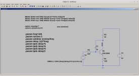
Thanks for the file as a playground!
I played with it and added some stepped C1 values:
And the phase delay increments around the "250us zero-crossing" point:
The input level did not change it significantly. (Tried from 10mV to 500mV)
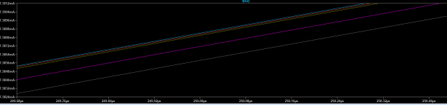
attachment #1: the "output" current (R2) phase variation
attachment #2: the input current phase variation
I played with it and added some stepped C1 values:
- 1pF
- 5pF
- 10pF
- 50pF
- 100pF
And the phase delay increments around the "250us zero-crossing" point:
- 8.5ns
- 10.7ns
- 85.5ns
- 106.8ns
The input level did not change it significantly. (Tried from 10mV to 500mV)
attachment #1: the "output" current (R2) phase variation
attachment #2: the input current phase variation
Attachments

Well done ...
We already have the delay by pf in that position Now we have to relate the transistor's own capacitance, and how it is going to
affect at certain signal level. From my experience acceptable values have to be below 0.05 ns x pf .
Of course this is a simple example , but we must do this tecnicque in our circuit .
Br
Last edited:
As long as you don't have a magic amp with CFA or VFA who doesn't give a damnOf course this is a simple example , but we must do this tecnicque in our circuit .
about all this. 😉
I'm not sure you meant this but this time
I removed the external miller cap C1 (set to 0) and
stepped the input signal level from 1mV to 500mV:
And phase delay changes again around the "250us zero-crossing" point:
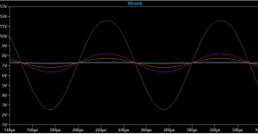
And the resulting Vout amplitudes.
I removed the external miller cap C1 (set to 0) and
stepped the input signal level from 1mV to 500mV:
- 1mV
- 10mV
- 50mV
- 100mV
- 500mV
And phase delay changes again around the "250us zero-crossing" point:
- +243.5ps
- -55.2ps
- -48.9ps
- -388.3ps
And the resulting Vout amplitudes.
Attachments
Last edited:
Ok .
I repeat, this technique has to be to evaluate your own circuit in
those nodes with the presence of transistors or other capacitances,
and of course with possible signal conditions.
Conclusions of your measurements:
the node is heavily afected by capacitances but you have chosen a good Cob transistor ,
Nor should we worry about what does not exist , if the chosen transistor have 0 pf
The problem does not exist
Last edited:
I used the same KSC2690 and get the model from the forum somewhere (attached).
And also my current "playground" setup.
And I also checked the phase delay changes around the 300us zero-crossing point:
Why it does this "inverted" directions in change..?
BTW: this is such a great feature of LTSpice, I didn't know it has them, thanks!
(I increased the ".option measdgt 10" paramter to be precise.)
And also my current "playground" setup.
And I also checked the phase delay changes around the 300us zero-crossing point:
- -82.6ps
- +39.1ps
- +53.7ps
- +437.4ps
Why it does this "inverted" directions in change..?
BTW: this is such a great feature of LTSpice, I didn't know it has them, thanks!
(I increased the ".option measdgt 10" paramter to be precise.)
Attachments
Sorry to interrupt this fascinating broadcast, but is this not the regular Miller-modulation (modulation of the c-b barrier and its capacitance by the changing Vcb)?
The right picture in #8 shows this clearly (phase shifts and amplitude variations) and is indeed troubling the performance of amplification tremendously.
The right picture in #8 shows this clearly (phase shifts and amplitude variations) and is indeed troubling the performance of amplification tremendously.
Cortez, I think I have not explained myself well, it is about knowing the delay
with a certain capacitance in that node. What is the real capacitance? ,
since the one that has the transitor at a certain voltage level.
with a certain capacitance in that node. What is the real capacitance? ,
since the one that has the transitor at a certain voltage level.
Sorry Ramcres I'm not sure about your last question.
Only the first one (#8) was stepping the C1 external capacitor.
All the other cases went with C1 = 0 and stepped just the input amplitude.
And yes, I checked the absolute delays ("Vout - Vin") as well
regarding the input level (stepped from 1mV to 500mV):
(MarsBravo: yes it's the good old Miller, nothing new, we know.)
Only the first one (#8) was stepping the C1 external capacitor.
All the other cases went with C1 = 0 and stepped just the input amplitude.
And yes, I checked the absolute delays ("Vout - Vin") as well
regarding the input level (stepped from 1mV to 500mV):
- 49.2363ns
- 49.9360ns
- 49.9794ns
- 49.9324ns
- 49.5517ns
(MarsBravo: yes it's the good old Miller, nothing new, we know.)
Sorry to interrupt this fascinating broadcast, but is this not the regular Miller-modulation (modulation of the c-b barrier and its capacitance by the changing Vcb)?
The right picture in #8 shows this clearly (phase shifts and amplitude variations) and is indeed troubling the performance of amplification tremendously.
You are right , and you are welcome .
That is straithening things up, and the various seasoned electronic heroes on this platform are accentually invited to join the discussion (Scott, Jan, Nelson, Bonsai, ?; jtnaf), because this is at the core of all issues: 'On Amplification'. Engage!
This is not of general interest, many because they do not know what we
are talking about, others because they do not want it to be known,
others because they are faithful to the idea expressed by Mooly in this comment that I read today.
are talking about, others because they do not want it to be known,
others because they are faithful to the idea expressed by Mooly in this comment that I read today.
As you can see the feedback can solve any problem, even defy the laws of physics, make anything ,perfect and in the same time.Any basic audio circuit should should cope with massive differences in hFE whether it is 50 or 500, that is the beauty of negative feedback... it irons all those differences out. BR
Last edited:
- Home
- Amplifiers
- Solid State
- How to neasure jitter in circuits.For advanced