Hi,
I want to model a 2.5" driver in a dipole waveguide, is there any way I can generate polar plots from 0 degrees to 180 degrees? Just like 2.5 TB driver in JBL waveguide like this:-
http://www.martinsson.cc/blog/images/W2_802_SE_2386_REAR.jpg
http://www.martinsson.cc/blog/images/NB24_frontview.jpg
http://www.martinsson.cc/blog/images/NB24_sideview.jpg
http://www.martinsson.cc/blog/images/NB24_topview.jpg
All images from the blog
Martinsson's Blog
More specifically, can hornresponse do it?
Thanks and Regards.
WA
What's your thinking behind this? It seems a little counter-productive to me. The polar plot is not going to be one thing or the other and seems like the worst of all possible combinations?
I am checking the possibility of a Nola Brio kind of a system where the highs are handled by a small fullranger in a waveguide (dipolish). Have a 2 or 3 octave or more overlap with omni driver to handle the lows.
A dipole "should" look the same in both directions. This will never do that. It's a horn(wg) without a back chamber.
//
//
What if we point back chamber to same as front waveguide making something like Manger Diskus (that was bipole).
Here is a pictures from the opening post, that tell the story
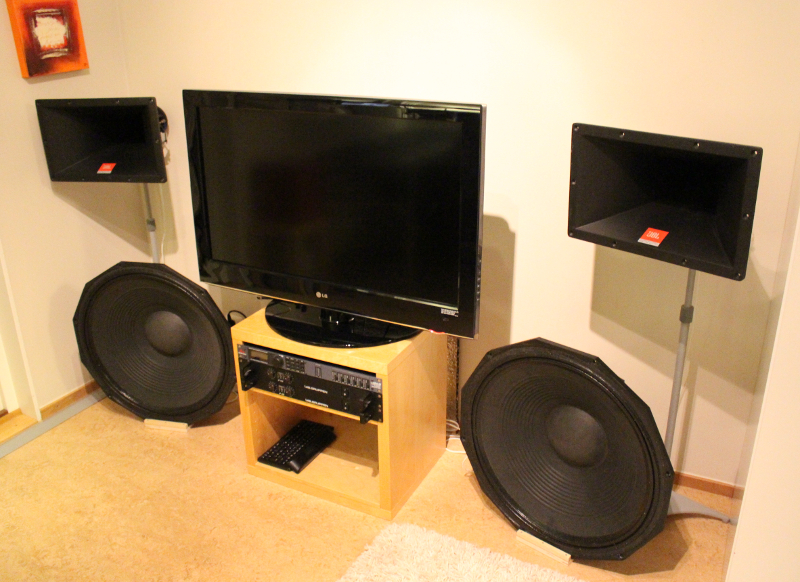
From Martinsson's blog Martinsson's Blog
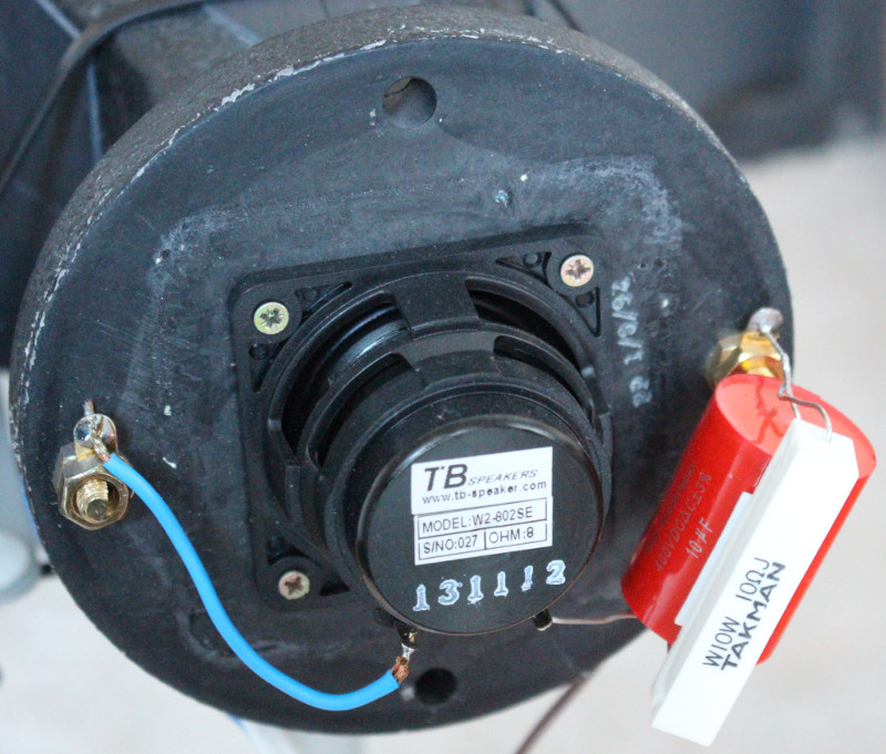
The horn driver is a 2" TangBand cone driver. Bass driver are nude 18" cones - all tucked deep in the corner of the room.
This construction has actually very little to do with a dipole radiation pattern. Front and back radiation are totally different because of the horn vs. magnet making reflections/interferences, and for the bass the corner loading is huge.
I can't see any way to model/simulate these. And neither can I see any "sense" in either.
From Martinsson's blog Martinsson's Blog
The horn driver is a 2" TangBand cone driver. Bass driver are nude 18" cones - all tucked deep in the corner of the room.
This construction has actually very little to do with a dipole radiation pattern. Front and back radiation are totally different because of the horn vs. magnet making reflections/interferences, and for the bass the corner loading is huge.
I can't see any way to model/simulate these. And neither can I see any "sense" in either.
and for the bass the corner loading is huge
I've tested some very large corner loaded woofers, and there still a large notch in the power response on the border of the cone in the LF.
In nearfiel few cm and 90¤? For sure yes, but total sound power at listening spot/area is what we listen to.
Boundary effects
How Do Boundaries Affect Loudspeakers?
When a dipole that makes low frequencies is pushed in the corner, the backside -sound gets 9dB boost relative to frontside + direct radiation. Sum is something less and with negative polarity and delay! The louder backwave will dominate in the measurement and perceived sound power, wild comb filtering starts then at higher freq.
Last edited:
In nearfiel few cm and 90¤? For sure yes, but total sound power at listening spot/area is what we listen to.
Boundary effects
How Do Boundaries Affect Loudspeakers?
When a dipole that makes low frequencies is pushed in the corner, the backside -sound gets 9dB boost relative to frontside + direct radiation. Sum is something less and with negative polarity and delay! The louder backwave will dominate in the measurement and perceived sound power, wild comb filtering starts then at higher freq.
It is a good explanation, i've bugged few seconds on the "dipole moment" because the moment signification in French is "momentum"
 reading a langage and think with another one is funny sometimes.
It seems to be a narrow directivity system, which is not a bad idea in a small space, but the woofers should be bigger in order to have a narrow directivity under the the horn BW, the only way to avoid reflexions is to don't create them IMHO.
It is a good explanation, i've bugged few seconds on the "dipole moment" because the moment signification in French is "momentum"
I've found the traduction, it is "Moment dipolaire" should be written "dipolar moment" in English... my eyes have stopped to spin
But it must be written "dipole moment"

- Home
- Loudspeakers
- Multi-Way
- How to model a driver in a dipole waveguide?