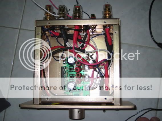
I have recently bought the Autocontruire TA2020 module and DIY a int. amp. I power it by a SLA battery. It sings! However, it seems that the mid-range is not thick enough. I wonder if I can get better sound by replacing the input caps and power caps. Anybody have experience on it?
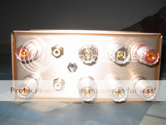


Sorry I don't have a reply to your original questions, but I would love to know where you got that wonderful little enclosure.
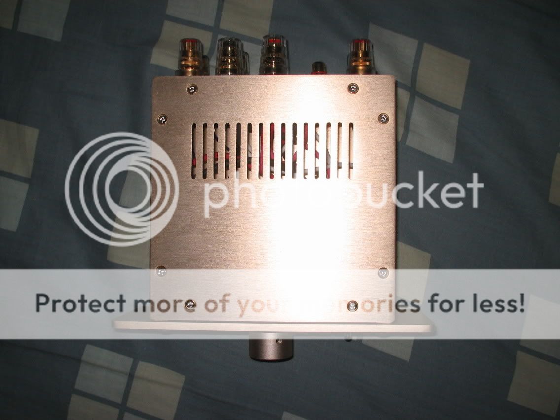
Nice job, btw.
Nice job, btw.
I would replace the power supply caps with Blackgates rated at 1000uf 16v. They are only 5 dollars a piece. You could try Sonicaps or Auricaps for the input caps. I find sonicaps better and cheaper. If you think the bass output is to your liking than use 2.2 uf otherwise use 3.3uf for the input caps. I hope this helps out.
theAnonymous1,
I got the case from a local shop in Hong Kong for about US$25. Seems it is not available on the internet. So you might be unable to get an identical one.
HolyGhostFire20.
Is it a good idea to reduce the value of the power supply caps from 2200uf to 1000uf? It seems that most people when modding their kits replace caps of smaller values to some of larger values. So is it better to replace the power caps with something like 3300uf or 4700uf?
I am very interested in Sonicaps. Could you tell me whether I can get it on the web?
Many thanks!
The sonicaps can be purchased at http://www.soniccraft.com/parts/capacitors.htm I don't know how much shipping costs will be worldwide. You could go higher on the uf value of the blackgate caps, but I find it isn't needed. The highest I would go for the blackgates is 2200uf. I hope this helps.
I power it by a SLA battery. It sings! However, it seems that the mid-range is not thick enough.
Exactly my findings! Try an SMPS, you should be pleasently surprised! 😉
Nuuk said:
Exactly my findings! Try an SMPS, you should be pleasently surprised! 😉
I'm happy that you posted this answer as I'll get my Autocostruire TA2020 next monday and really don't want the mid to be thin

I'll use a good SMPS. I can adjust it from 12 to 15 volt. What is the setting of your SMPS ? I wonder if setting it at 13V would be safe ? (13.5 V is supposed to be the max).
Regards,
I'll use a good SMPS. I can adjust it from 12 to 15 volt. What is the setting of your SMPS ? I wonder if setting it at 13V would be safe ? (13.5 V is supposed to be the max).
I'm currently running the SMPS at 12.4 volts. I think that 13 would be fine but I'm not sure how much a volt matters in the context anyway!
 I guess it comes down to the rest of the system and how efficient the speakers are! 😉
Nuuk said:
I'm currently running the SMPS at 12.4 volts. I think that 13 would be fine but I'm not sure how much a volt matters in the context anyway!
I'll play safe and set it to 12.5-12.8 volts, depending on how much this change affect the sound.
Thanks !
It seems the Autocostuire.it version.
I never tried it, but I dislike the aircored inductor (the red cilinders). A try that is wort is to use ferrite core inductors (panasonic, Tayo Yuden etc) as suggest by Tripath.
I never tried it, but I dislike the aircored inductor (the red cilinders). A try that is wort is to use ferrite core inductors (panasonic, Tayo Yuden etc) as suggest by Tripath.
Nuuk said:Daniel, on another Autostriure subject, what value feedback resistors are you using?
As I mentioned, my board will arrive next Monday. My speakers are 4 ohm and the amp will be configured according to this fact.
As I mentioned, my board will arrive next Monday. My speakers are 4 ohm and the amp will be configured according to this fact.
Oh yes, I forgot you haven't got it yet! 😉
Sorry to bump an old thread -- but thought would be better to keep autocostruire / audiodigit mods in one place....
I've just ordered one assembled (it's my first DIY experience, and I'm letting myself in gently), but plan on the following mods:
1. Volume pot bypassed/removed (using pre with an alps RK40)
2. Input caps changed to Audyn Cap Plus 2.2uf
3. Power supply caps changed to either Black Gate or Elna Cerafine. The stock ones are rated 2200uf 35v. But wondering if I can go as low as 16v, and change the value to 1000uf? Any thoughts?
4. Also wondering if it is worth changing the various output caps (there are six of them, 0.22uf-0.33uf) with polypropylene caps such as the Audyn Cap plus??
thanks for any advice....
Tripath TA2020
The max volts for the TA2020-020 Tripath chip is 13.6V...
This is due to the internal MOSFET pairs are only rated for 16V. O/P Overshoots could exceed this if the loads are very inductive, and you are using the earlier eval. board form Tripath at voltages higher than 13.6v
The Tripath Eval board in the pics above is the latest revision and will have the mods below done already. I include them for guys who have the earlier eval. board like I have....
For reliability at high powers into low impedance loads, (sub 4 ohm) add two low ESR 220uF caps, at the supply pins of the chip...Actually on the supply pin and actually on the earth pins of each channel... (two caps, mounted accross the two earth and supply pins....)
This update also improved my 'mid' presence I find.....
Ensure you have D1 to D4 in place...Check out www.tripath.com and the product data-sheets for the TA2020 Eval board and the chip itself for more details on 'overshoot protection'
I am currently using an early Eval. board from 1999 in my car running into parralleled 4 ohm speakers with complete success. Each O/P is 'seeing' slightly under 2 ohms read by my digital meter.
The board has been 'updated' with the overshoot protection. The vehicle voltage sometimes creeps up to 14.5V after a long run, but the TA2020 runs cool even at high volumes. Its attached to an old Pentium heatsink, without the fan.
Thx for the reply Alistair. I won't actually have the evaluation board, but autocostruire / audiodigits implementation of it.
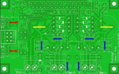
The file attached is the pcb with the planned (?) upgrades marked:
- The red lines are the input caps. Stock, these are 2.2uf 50v. I plan to upgrade these to 2.2uf poly caps (Audyn Cap plus 2.2uf 800V).
- The yellow lines are the power caps. Stock, these are 2200uf 25v. But I'm wondering if I can go as low as 16v (which I gather from Alistair that I can), and for the value if something like 1000uf would be OK? (this would make BG caps an option).
- The blue lines are the output caps. Stock, these are 0.33uf 63v. What I'm wondering here is if polypropylene caps such as the Audyn Cap plus would be an upgrade?
In advance, please please forgive my total ignorance. I'm a TOTAL newbie on a very steep learning curve..... (my day job is as a journalist, having failed maths and physics at school).
Attachments
Supply rail caps...
Personally, I wouldnt use 'Audiofile' type caps here....
They are important for IC Protection, as they work in conjunction with the 8 diodes accross the output pins, to prevent 'Overshoot' of the output pin due to the inductive load of the speaker and the series inductor of the Lo pass filter....These chips work at very high frequencies, continuously varying between 100Khz and 1Mhz as I recall, in a near square-wave, so overshoot is a very real issue which can and does destroy chips...Been there, Done that!
They MUST be Low ESR types, Good quality the sort for high temp service in SMPS are pretty cool, Panasonic make a good range of this type......
I would advise Voltage rating of 25V and I would stick to the 'stock' value of 2200uF--No advantage in going smaller here...
Looking at the board layout, the caps are FAR too far away from the supply/earth pins, Tripath recommend in their documentation that they must be placed as close to if not actually on these pins to be properly effective at their job, (Protection, Not Decoupling!)........I would leave the rail-caps as they are, and add a couple of 220uF 25V Lo ESR Directly On The Power to Ground Pins for each output channel...
(This was the problem with this chip and the higher power TA2022 and one reason why its being phased out The pinout is a Swine to work with, and comply with the requirements like this one! I spent some weeks back in 2000, designing round both these chips, and actually advised tripath of this issue, and they sheepishly admitted their mistake, but it was too late at the Production stage....)
Why use such large Polyprop High Volt caps at the Input??
--No point as far as I can see, apart from the sheer size as they would then Look impressive, but I fear they may sound worse than a cheepie lecylytic in this position ...
The Output decoupling caps, are to remove the HF from the wave-form. I experimented with these, and found the 'stock 1uF most suitable. Later designs have used as small as .22uF, especially in the parralleled output 100W set up for the 2020 into 2 Ohms (Output Voltage Offset Servo circuit needed for this...)..
Have you seen the TA2020-020's replacement? The TA2024 I believe, A 25W SM device with the 'die' uppermost and pins on either side. Much better pinout to work around!
- Status
- Not open for further replies.
- Home
- Amplifiers
- Class D
- How to mod my Autocontruire TA2020?