So I just read this 12 year old thread from the start. I have to say the pedantic exchanges between Bob Cordell and me are a very boring read. It felt important at the time but now it just seems a waste of bytes in a server somewhere.
mikelm writes: "Now, perhaps it would seem that i/p filters can play a part in achieving good phase margins - or rather they always did, but some of us just hadn't realised it."
Yes.
mikelm writes: "Now, perhaps it would seem that i/p filters can play a part in achieving good phase margins - or rather they always did, but some of us just hadn't realised it."
Yes.
I don't think you are measuring phase margin in this way.
The phase margin has relevance to the phase shift inside the loop.
All you have done is create a new 'input' signal (top of the i/p cap).
You must measure the phase shift as the difference in phase between the two signals going to the summer/difference stage of input and feedback.
In this case, those points are the base of Q2 and Q3, that is where the phase shift matters.
This is not influenced by the presence or absence of the i/p cap.
Think about it: do you think you can make an unstable circuit stable by phase shifting the output of the signal generator?
That is the same as switching the signal generator on 1ms later.
Jan
Last edited:

Input filters are outside the feedback loop so I don't see how they could impact the loop gain/phase or the gain/phase margin.Now, perhaps it would seem that i/p filters can play a part in achieving good phase margins - or rather they always did, but some of us just hadn't realised it.
It's hard to tell with the connect-by-label, but it seems to me that you're simulating the closed loop frequency response. Not the open loop response.
The best way I've found of simulating the loop gain is to use an "infinite" LC filter in the feedback loop to set a cutoff frequency in the mHz or uHz region. You can see that in action here: https://neurochrome.com/pages/stability It's not a 200% bullet-proof method in that it still requires you to find a good spot within the loop to insert the filter. Basically you want a spot where the filter can be driven by a low impedance and loaded by a high impedance. Also, I think it's possible for this method to miss potential trouble if the input presents a significant reactive load. I use this method along with transient simulations of the step response. I then follow up with lab measurements as well.
I wonder if one could use a VCVS to introduce a disturbance within the loop and tease the loop gain out from that. I've done something similar in the lab using a Rogowski coil as the injector.
Tom
No. The input can be anything you want. The phase margin is NOT the phase shift.OK - thanks for your replies.
I get it now - The i/p has to be flat to get an accurate result.
The phase margin is a difference in phase between an input point and a feedback point, as mentioned the base of Q2 and Q3.
The actual phase of the input is of no consequence. Is that clear or should we discuss some more?
Did you read Tom's post above, where he said:
"Input filters are outside the feedback loop so I don't see how they could impact the loop gain/phase or the gain/phase margin."
Edit: if your result for phase margin changes with the i/p cap value, you are not measuring phase margin correctly.
Jan
In fact, you do not need to break the loop, use a transformer or a network analyzer to measure the loop gain; in principle at least: in practice, it is not going to be that easy.
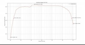
To illustrate the method, here is a comparison between the classical method, based on loop breaking and a (simplified) Tian probe, and the "direct" method, based simply on the observation of the voltages on an untouched amplifier:

In the second circuit, the open loop gain is calculated by dividing the output voltage by the input voltage: no rocket science. To take the feedback network into account, a 1/10 factor is added.
As you see, both curves are almost perfectly overlaid. There are small divergences, increasing at higher frequencies: they are caused by the loading effect of the (-) input.
If the impedance is known, it can be added in parallel with R4, to increase the accuracy of the measurement.
Of course, in practice things are going to be much trickier than in sim, mainly because the m-p voltage will be tiny due to the high open-loop gain, and will generally need to be acquired in a differential mode.
This can be addressed by placing a good, high gain, high bandwidth differential lab amplifier in front of the oscilloscope: nothing insurmountable.
You can then work out the gain and phase difference manually for each frequency of interest; a bit clunky, tedious, but certainly doable, and with some precautions, a phase accuracy of only a few degrees can be attained.
Of course, you have to be careful: the differential measurement amplifier needs to have a very high input impedance, and a negligible capacitance otherwise loading effects will dominate, and the AUT might be upset to point of becoming unstable, but this shows that with some determination, such a measurement is possible is possible without altering the AUT
To illustrate the method, here is a comparison between the classical method, based on loop breaking and a (simplified) Tian probe, and the "direct" method, based simply on the observation of the voltages on an untouched amplifier:
In the second circuit, the open loop gain is calculated by dividing the output voltage by the input voltage: no rocket science. To take the feedback network into account, a 1/10 factor is added.
As you see, both curves are almost perfectly overlaid. There are small divergences, increasing at higher frequencies: they are caused by the loading effect of the (-) input.
If the impedance is known, it can be added in parallel with R4, to increase the accuracy of the measurement.
Of course, in practice things are going to be much trickier than in sim, mainly because the m-p voltage will be tiny due to the high open-loop gain, and will generally need to be acquired in a differential mode.
This can be addressed by placing a good, high gain, high bandwidth differential lab amplifier in front of the oscilloscope: nothing insurmountable.
You can then work out the gain and phase difference manually for each frequency of interest; a bit clunky, tedious, but certainly doable, and with some precautions, a phase accuracy of only a few degrees can be attained.
Of course, you have to be careful: the differential measurement amplifier needs to have a very high input impedance, and a negligible capacitance otherwise loading effects will dominate, and the AUT might be upset to point of becoming unstable, but this shows that with some determination, such a measurement is possible is possible without altering the AUT
Attachments
Elvee’s method is what I use.
BTW the input filter is in the loop, strictly speaking, as the “loop” response depends on the impedance at the input. A signal on either differentiator input will affect the others input via the differential impedance.
This is a relatively minor effect.
BTW the input filter is in the loop, strictly speaking, as the “loop” response depends on the impedance at the input. A signal on either differentiator input will affect the others input via the differential impedance.
This is a relatively minor effect.
Your circuit has two inputs. One you feed your music signal into and the other you feed the amplifier’s output into.OK - thanks for your replies.
I get it now - The i/p has to be flat to get an accurate result.
It’s the phase response of the latter one (the feedback input) that matters.
If you could disconnect the feedback path from the output and inject a signal into it, whilst keeping the dc operating points of the circuit the same, you would see the loop gain and phase at the output.
In a simulator you can achieve this by inserting an ac voltage source in the feedback path and then displaying the ratio of the signals on each side of it. That’s what Elvee’s simplified Tian probe does.
Hi Traderbam, I'm glad you raised this point because I was just thinking that I cannot imagine than amp with a 1 meg resistor in series with the input would have a stability problem - an exaggerated example I know, but I think the exaggeration clearly demonstrates the principle.Elvee’s method is what I use.
BTW the input filter is in the loop, strictly speaking, as the “loop” response depends on the impedance at the input. A signal on either differentiator input will affect the others input via the differential impedance.
This is a relatively minor effect.
It's OK Jan, I get what your saying ( with the exception of the point that Traderbam raised )No. The input can be anything you want. The phase margin is NOT the phase shift.
The phase margin is a difference in phase between an input point and a feedback point, as mentioned the base of Q2 and Q3.
The actual phase of the input is of no consequence. Is that clear or should we discuss some more?
Did you read Tom's post above, where he said:
"Input filters are outside the feedback loop so I don't see how they could impact the loop gain/phase or the gain/phase margin."
Edit: if your result for phase margin changes with the i/p cap value, you are not measuring phase margin correctly.
Jan
I don't agree to TB's point either. The input network is not in the loop.
Thought experiment: let us re-locate that R-C inside the signal generator box without telling anyone.
Does it ruin the amp stability?
Asking the question is answering it.
But, TB, if you read this, I will not engage in a discussion on this. Sorry.
Jan
Thought experiment: let us re-locate that R-C inside the signal generator box without telling anyone.
Does it ruin the amp stability?
Asking the question is answering it.
But, TB, if you read this, I will not engage in a discussion on this. Sorry.
Jan
Thought experiment 2: Can you imagine an amp with 1meg ohm in series with the input being unstable ?
Thought experiment 3: Can you imagine the same amp with 1m ohm in total in series with the input being unstable ?
Thought experiment 3: Can you imagine the same amp with 1m ohm in total in series with the input being unstable ?
I’ve found loop gain analysis with LTSpice remarkably good. If never built an amp that oscillated when the spice analysis said it was ok. I has a parasitic issue on the kx-amp (now withdrawn and replaced with the kx2-Amp ) but that had nothing to do with loop gain/phase stability. In audio, the frequencies of interest are low enough for loop gain sims to be pretty accurate. Once the amp is built, it’s very easy to confirm the performance practically by looking at the small signal (ie 1-2 V out) square wave response into a suitable load. If it’s well behaved on the scope trace, it’s almost certain your amps loop gain and phase are well behaved.
Oh yes I can, for both situations, and I could certainly find real world examples to demonstrate it.Thought experiment 2: Can you imagine an amp with 1meg ohm in series with the input being unstable ?
Thought experiment 3: Can you imagine the same amp with 1m ohm in total in series with the input being unstable ?
And no, the input network is not in the loop, however there are cases where it will influence the loop gain and closed-loop gain: think of an inverting amplifier: the network will become part of Rg, determining the gain.
For a non-inverting amplifier, it should have no effect but some marginal parasitic effects can creep in and slightly modify the result (parasitic capacitances from various nodes for example). The same effects can cause oscillation when the source impedance is unreasonably high, like 1Meg
... and then it is in the loop. We were discussing a specific example.think of an inverting amplifier: the network will become part of Rg, determining the gain.
Jan
I use the method described in the attached pdf
Attachments
-
 Screenshot_20221103-065047_Photos.jpg74.1 KB · Views: 85
 -
 Screenshot_20221103-065105_Photos.jpg83.6 KB · Views: 73
 -
 Screenshot_20221103-065121_Photos.jpg73.6 KB · Views: 81
 -
 Screenshot_20221103-065207_Photos.jpg128.5 KB · Views: 91
 -
Use Op-Amp injection for Bode Analysis.pdf212.1 KB · Views: 126
-
 Screenshot_20221103-065019_Photos.jpg625.8 KB · Views: 85
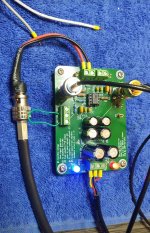
Thanks Stuart, that's very useful! I have a Bode100 which uses a special injection transformer https://www.omicron-lab.com/fileadm...sories/B-WIT_100/B-WIT-Brochure_V1.1-1403.pdf
The xfrmr goes down to about 1Hz which is useful, but as you said, it'll cost you!
(BTW The inside is just a ferrite toroid with a bunch of wire so you could reverse engineer it for less cost).
The B-LFT100 even goes down to 0.1Hz, but I have no idea how much that cost.
Jan
The xfrmr goes down to about 1Hz which is useful, but as you said, it'll cost you!
(BTW The inside is just a ferrite toroid with a bunch of wire so you could reverse engineer it for less cost).
The B-LFT100 even goes down to 0.1Hz, but I have no idea how much that cost.
Jan
Are you also considering the differential impedance of the input stage? Not a parasitic effect.For a non-inverting amplifier, it should have no effect but some marginal parasitic effects can creep in and slightly modify the result (parasitic capacitances from various nodes for example). The same effects can cause oscillation when the source impedance is unreasonably high, like 1Meg
What I mean is that the impedance seen at the inverting input is affected by the impedance of components at the non-inverting input, because the two are linked via the base-emitters of the input transistors.
It does have an effect on the loop gain (not on the OL gain, obviously).
This can be shown here, on the "regular" measurement setup:

With 1K , an additional 20dB of loop gain is eaten up, which is normal.
With the unaltered setup, no difference is visible:

But the curve equation still assumes an ~infinite impedance. This setup yields the open-loop gain, which remains the same, but it has to be corrected by paralleling R4 and R5.
If it is done, the look of the curve will match the green one on the graph above
This can be shown here, on the "regular" measurement setup:
With 1K , an additional 20dB of loop gain is eaten up, which is normal.
With the unaltered setup, no difference is visible:
But the curve equation still assumes an ~infinite impedance. This setup yields the open-loop gain, which remains the same, but it has to be corrected by paralleling R4 and R5.
If it is done, the look of the curve will match the green one on the graph above
- Home
- Amplifiers
- Solid State
- How to measure phase margin of an amplifier?