Hi Karl,
Thank you for you input. I have used your example of 1 kHz frequency input from CD to the scope.
Vertical ------>Set at 1 volt/div
Horizontal--->Turn the timebase dial until I get the 5 squares for 1 cycle similar to your top channel display screen shot.
However, mine is not square like yours although the insert of the CD clearly stated it is at 1 kHz and it is a square wave just like track 67.
My test CD is "My Disc" 10045-2-t The Shefffield/A2TB Test Disc and the track that I was using here is Track 68.
Attachments
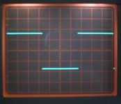
The good thing about this test/ check is that I now found out that the marking on the dial of the SEC/DIV is off.
The two black lines are the original came like that with the scope and it is overlaying both the 50 and 20 [us] millisecond/1000....this is very confusing when I tried following the manual to obtain base line.
But according to your example it should be at 0.2 millisecond. Now I have used a marker and made a spot under the 0.2 point on the dial. May be you can see it in the picture. It is at 12 o'clock I made the black dot on the transparent disc of the dial. That is the 0.2 ms with 0.5 ms on its left and 0.1 ms on its right.
Sorry about the quality of the picture. My camera is not very good with micro setting. My photo skill is not good at all.
Still waiting for the probe..
Attachments
Hi,
Does your test disc have a lot of different spot frequencies up to 20 khz. If so I would look at each one on the 'scope and make sure the timebase seems accurate. Do you have a multimeter with a frequency range on it. If you do check each track on the disc with that as well. Also if your meter measures small A.C. voltages accurately measure the output of your CD (choose a track recorded at as high signal as possible and make sure it is within the frequency range of the meter), and see if the RMS value shown by the meter agrees with the pk/pk value shown on the 'scope.
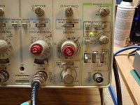
Is it possible that the switch or knob has been moved accidently on the 'scope. Might be worth seeing if it can be repositioned correctly, and now you know how to work the frequencies out you can be sure you get it in the right place. I see the cal knob does not line up with the attenuator one next to it--- may be nothing that !
I can't quite make out some of the text on the front panel but the top right knob, you want that on normal--no hold off. The left hand switch of the three at the bottom. This provides the timebase with a signal to trigger from. If you set it at ch1 it takes the signal from this channel only. Same for ch2. This is normally the way to use it, use channel one for measuring and trigger off ch1.
If you are using the two channels together, for example displaying the input and output of an amp then still use this mode. Provided the two signal you are looking at are "related" in terms of frequency and phase the display will be stable. Only use the "vert" mode triggering when the two inputs are unrelated. For example the output of your CD on channel 1 and perhaps say the secondary of a transformer on ch2. The vert mode will then give a stable display as it first shows ch1 triggered from ch 1 and then ch 2 triggered from ch2.
Again hard to make out but have you got it in "add" mode. The switch above ch2 attenuator. You want "alt" or alternate. If you turn the timebase speed right down ( and with both channels enabled )you will see alt sweeps ch1 and then ch2. Chop will appear to show both sweeping together, only use this at very low speeds where it make the display easier to view. Add numerically adds the signal of ch 1 and ch2 ( Quite useful for taking differential measurements ) If you have ch1 and 2 displaying the same signal at the same attenuator settings then add will show the sum of these- try it. Also if you then "invert" channel 2 the phase is inverted (180 degree shift). If you now add these together the result -- if the attenuators and calibration are correct--will be zero. Again try it !
That should keep you busy for half an hour or so 😉
Does your test disc have a lot of different spot frequencies up to 20 khz. If so I would look at each one on the 'scope and make sure the timebase seems accurate. Do you have a multimeter with a frequency range on it. If you do check each track on the disc with that as well. Also if your meter measures small A.C. voltages accurately measure the output of your CD (choose a track recorded at as high signal as possible and make sure it is within the frequency range of the meter), and see if the RMS value shown by the meter agrees with the pk/pk value shown on the 'scope.
Is it possible that the switch or knob has been moved accidently on the 'scope. Might be worth seeing if it can be repositioned correctly, and now you know how to work the frequencies out you can be sure you get it in the right place. I see the cal knob does not line up with the attenuator one next to it--- may be nothing that !
I can't quite make out some of the text on the front panel but the top right knob, you want that on normal--no hold off. The left hand switch of the three at the bottom. This provides the timebase with a signal to trigger from. If you set it at ch1 it takes the signal from this channel only. Same for ch2. This is normally the way to use it, use channel one for measuring and trigger off ch1.
If you are using the two channels together, for example displaying the input and output of an amp then still use this mode. Provided the two signal you are looking at are "related" in terms of frequency and phase the display will be stable. Only use the "vert" mode triggering when the two inputs are unrelated. For example the output of your CD on channel 1 and perhaps say the secondary of a transformer on ch2. The vert mode will then give a stable display as it first shows ch1 triggered from ch 1 and then ch 2 triggered from ch2.
Again hard to make out but have you got it in "add" mode. The switch above ch2 attenuator. You want "alt" or alternate. If you turn the timebase speed right down ( and with both channels enabled )you will see alt sweeps ch1 and then ch2. Chop will appear to show both sweeping together, only use this at very low speeds where it make the display easier to view. Add numerically adds the signal of ch 1 and ch2 ( Quite useful for taking differential measurements ) If you have ch1 and 2 displaying the same signal at the same attenuator settings then add will show the sum of these- try it. Also if you then "invert" channel 2 the phase is inverted (180 degree shift). If you now add these together the result -- if the attenuators and calibration are correct--will be zero. Again try it !
That should keep you busy for half an hour or so 😉
I do not have any multimeter with frequency measurement.
I managed to get the 1 kHz square wave from the Sheffield Test CD. This time I am using an older Sony CD player that I bought for $2.0 in a jumble sale years ago instead of the DVD player.
Volts/DIV is set at 0.2
SEC/DIV is set at 2ms
See picure below
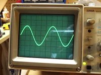
I also managed to test another CD with a 20 kHz sine wave track.
No picture for this one though.
Volts/DIV is set at 0.1
SEC/DIV is set at 10us...means 10microsecond? or 0.01ms?
The sine wave full cycle takes 5 squares on screen
5 X 0.01ms=0.05ms (5 squares on screen)
1 / Time in second= Frequency
convert ms to second 0.05ms / 1000 = 0.00005s
1 / Time in second = Frequency
1 / 0.00005 = 20000 Hz
Am I correct?
I managed to get the 1 kHz square wave from the Sheffield Test CD. This time I am using an older Sony CD player that I bought for $2.0 in a jumble sale years ago instead of the DVD player.
Volts/DIV is set at 0.2
SEC/DIV is set at 2ms
See picure below
I also managed to test another CD with a 20 kHz sine wave track.
No picture for this one though.
Volts/DIV is set at 0.1
SEC/DIV is set at 10us...means 10microsecond? or 0.01ms?
The sine wave full cycle takes 5 squares on screen
5 X 0.01ms=0.05ms (5 squares on screen)
1 / Time in second= Frequency
convert ms to second 0.05ms / 1000 = 0.00005s
1 / Time in second = Frequency
1 / 0.00005 = 20000 Hz
Am I correct?
Attachments
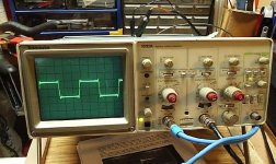
Thats it ! You will see your squarewave looks identical to the one I posted, slow risetimes and ringing from the filters in the player.
Now you have a 'scope I think a function or signal generator would be next on the shopping list. I have attached another image, this is a squarewave from a function generator. Notice how fast the rise time are compared to the CD. This is really the sort of signal you need for measuring amps etc, but having said that try your test disc squarewave through an amp. The function generator I use covers from 0.1 hz to 2 Mhz sine/square and triangle waveforms with a max output of around 7 volts RMS.
You mentioned at the start about checking your amp. The only point to watch is as I mentioned earlier, that if the 'scope is connected to mains earth then the probe earth becomes a "shorting link", to anything referenced to earth. That does not read well does it ! If your JLH psu ground is also connected to mains earth, then touching the probe earth to say the positive rail will apply a dead short across it. If in any doubt measure on DC then AC volts between the points you want to apply the ground wire first.
Try some measurements on your amp, perhaps the ripple on the rails.
Regards Karl
Attachments
Hi Karl,
I have just finished replacing all 4 outputs MJ21194 and emitter resistors of the faulty JLH. I think they are all blown as the emitter resistors were all blown apart to pieces
I replace them with 2n3055 (from dismantled 1969 JLH my first diy) of what I have in hand and the emitter resistors are 5% 0.10 ohm 2 W.
Use the variAC bring up the power slowly. The DC offset is about 110mV start up and slowly going down and the Iq is at 130mV across one of the emitter resistor. Too tired to carry on and wait until it warm up. Will continue...
But what to do to measure ripple on the rails? The rail voltage is at 24V. This is a CLC PSU not regulated.
If I want to put the 1kHz square wave through the amp do I just connect the output from the CD player to the amp just like I connect it directly to the scope. Do I then connect the 1X probe's tip both ground and tip to the speaker outputs?
Best Regards,
Hi Chris,
Yes to measure the rail ripple connect the 'scope negative to the zero volt line. Is all this about being careful where you put the ground wire putting you off ? And with the 'scope on AC coupling (so you can see small AC signals sitting on top of a large DC component) for the Volt/Div attenuator (set around 5 volts/div to start) and a timebase speed such that a couple of cycles at 50/60 hz will fit on the screen connect the probe tip to the positive rail starting at the rectifier and working toward the amp.
You will be able to see how the ripple voltage increases as you alter the quiescent current of the amp. Try also measuring directly on the speaker outputs with the input to the amp shorted and see if there is any measurable ripple at 50/60 hz. If you feed the squarewave into the amp remember to use a pot, or feed it from your preamp so you can control the level.
Regards Karl
Hello there,
Yes I am still a bit shy to poke the probe into the PSU. When you say " connect the 'scope negative to the zero volt line " do you mean the shield of the 1 X probe and the not the a connector on the front of the scope with a label GND?
Best Regards
Yes I am still a bit shy to poke the probe into the PSU. When you say " connect the 'scope negative to the zero volt line " do you mean the shield of the 1 X probe and the not the a connector on the front of the scope with a label GND?
Best Regards
Hi Chris,
They are one and the same, but-- there's always a but, when measuring HF and we are talking R.F. really grounding of the probe becomes important, so important that even the earth lead on the scope probe will give incorrect readings.
But we don't need worry about any of that here.
I know mains arrangements vary the world over, but you are not going to blow yourself up 😀 , just remember if in doubt to check with your meter that no voltage exists between the points where you intend to clip the earth lead and the 'scope.
If the case of your 'scope is earthed ( and it should be ) then this means that the scope probe earth lead is also connected to mains earth. Measure on your meter to prove to yourself it is.
If your amp case is earthed and you have connected your PSU zero volt line to the amp case then this too is earthed.
So connecting the scope to the amp case or zero line is fine- but if you clipped the earth of the probe to say the positive rail can you see how that would short out the PSU. From the rail positive through the probe earth wire to earth in the mains, back through the amp earth in its mains lead to the zero volt line-- a dead short.
The input impedance of the scope is high, 1 Meg, or 10Meg with a 10/1 probe so no problems there. The probe tip wont cause any current to flow, so stick it on the rails and have a measure.
In fact if both items are earthed as I describe above you don't actually even need the scope probe earth lead ( the probe clip) connected, it's done anyway through the mains leads, but you will find the "noise" ( on the 'scope screen ) decreases if you ground properly when measuring.
Can we expect a "ripple reading" 😀 😀 by the end of the day.
Edit, Chris, I saw your post on the JLH thread. I don't know what "variation" you are using but a single ended input stage draws its current supply from the output "midpoint" -- is this causing the current "inequality" you mention.
Hi Karl,
The version of the high power is here:
http://www.diyaudio.com/forums/showthread.php?postid=1517808#post1517808
By the time I try it tonight after work it will be two in the morning in your part of the world I think.🙂
I was hoping the moderators would have merged that thread with this one the other day but I guess my english is not good enough to express that point clear enough to be understood precisely.
I will be checking that feedback resistor 2.7k (R8) might need a cap across it as the others were saying. But I only have a 100pf smallest at hand. Do you think that can help?
Best Regards,
Hi Chris,
See your on line, is it the drop across R15/16 that is not equal.
Edit, Well you were ! 😉
See your on line, is it the drop across R15/16 that is not equal.
Edit, Well you were ! 😉
Had chance to read your other post again. What DC voltage have you at the emmiter of Q4, just interested on that one 🙂
I suspect the outputs are not sharing the current equally for a couple of possible reasons.
1. The characteristics of the transistors vary enough that the very low 0.1 ohm resistors are unable to allow the currents to equalise properly. Although the efficiency would be slightly worse perhaps try 0.33 ohms or 0.47 ohms and see if that helps.
2. Are the outputs thermally coupled i.e. on the same heatsink ? The characteristics change wildly with changes in temperature.
Adding a cap across R8 won't change the DC conditions unless the amp was unstable and oscillating to begin with. A small current flows through R8 to provide Q4 with its correct operating conditions and this will very slightly ( not what you are getting ) imbalance the current in the output halfs (Q1/Q1A and Q2/Q2A combined).
Hi Karl,
The top and bottom half are not on the same heat sink but they are identical heat sinks though.
Emmiter voltage of Q4 will be measured across the emmiter and ground? Same as the base of Q3 and ground? I hope it is not too stupid a question.
Best Regards,
The top and bottom half are not on the same heat sink but they are identical heat sinks though.
Emmiter voltage of Q4 will be measured across the emmiter and ground? Same as the base of Q3 and ground? I hope it is not too stupid a question.
Best Regards,
Hi Chris,
Emmiter of Q4, goes to junction of R6/8 and collector of Q6.
Am I looking at the right circuit ? 😉
Emmiter of Q4, goes to junction of R6/8 and collector of Q6.
Am I looking at the right circuit ? 😉
Sorry Karl,
That's my mistake I thought emitter is the one that with the arrow 😀
So it is to measure voltage across the the collector of Q6 junction of Q4 emitter and R6/8 and ground then? Thank you for your effort. Will post result later on tonight..
Cheers,
That's my mistake I thought emitter is the one that with the arrow 😀
So it is to measure voltage across the the collector of Q6 junction of Q4 emitter and R6/8 and ground then? Thank you for your effort. Will post result later on tonight..
Cheers,
Hi Chris,
Have a look at this, just been posted today-- if I knew (could get to work more like 🙂 ) I would put a link in.
Look in the " everything else " forum, the thread you want is "Oscilloscope in audio tutorial" post # 57. Could be just what you want.
As I type this it's next one to this thread 😉
Have a look at this, just been posted today-- if I knew (could get to work more like 🙂 ) I would put a link in.
Look in the " everything else " forum, the thread you want is "Oscilloscope in audio tutorial" post # 57. Could be just what you want.
As I type this it's next one to this thread 😉

Mooly said:Had chance to read your other post again. What DC voltage have you at the emmiter of Q4, just interested on that one 🙂
.
Hi Karl,
Measured across the emitter resistors (100m) after 20 minutes warm up.
Bottom half
For Q1 R14 ---> 49 mV
For Q1a R16 ---> 85 mV
Top half
For Q2 R13 ---> 37 mV
For Q2a R15 ---> 96 mV
The DC voltage of emitter of Q4 is 605 mV
DC offset stable around -6 mV at speaker outputs
The emitter of Q2a and speaker Vout is 100 mV
DC Supply rails +26.7 V and -26.7 V at C6 and C7
Best Regards,
Hi Chris,
That's fine, what I was getting at was to make sure C4 was not reverse biased at all -- it's not - just !
Going back to the current inequality- in percentage terms it's a lot. Do try higher value emmiter resistors, that might well do the trick, and even at 2 amps per transistor the loss is small. A 0.47 ohm 3 watt resistor (non inductive) would be fine.
No ripple voltage yet ! 😉 Get it measured. If you post the result here at least we know you lived to tell the tale.
- Status
- Not open for further replies.
- Home
- General Interest
- Everything Else
- How to measure JLH Class A with a Scope