What are you trying to read ?
If you only want to check their value you could use a resistor and a stopwatch.
If you only want to check their value you could use a resistor and a stopwatch.
The tolerances of big electrolytics are huge so accuracy is not the key here.
What voltage rating are the caps to be measured ?
What voltage rating are the caps to be measured ?
How to measure 10.000uF 63V capacitors?
My DVM can't have enough range😡
TIA
Felipe
By the way between others I also have a UNI-T UT139C DMM with a good range of features, reasonable build quality and protection for the price too, that can reach 100000uF.
~35 Euro on Ebay from mainland China or ~50 Euro from European stockists. Maybe its also useful info to you while the methods the other guys mentioned are valid and handy.
https://www.youtube.com/watch?v=Y3qwpJjq_M0
https://www.youtube.com/watch?v=3KP1pB4JdGw
Smaller uF range normally in those, up to 10000uF maybe. Check in your budget LCR models specs online for that characteristic.
- Build an astable multivibrator (oscillator) out of a 555 chip, this capacitor, and a 1% resistor. Measure the oscillator frequency, and use the equations in the 555 datasheet to convert from frequency to capacitance.
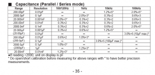
- Buy a DE5000 (link to EEVblog video), (link to eBay sales page). Capabilities are shown in attached image.
- Connect a 15 ohm resistor in series with the capacitor and drive the RC network with a 1kHz sinewave from your function generator. Connect your dual trace oscilloscope with Channel1= (function generator output) and Channel2=(Capacitor). The voltage division ratio gives you the capacitive reactance at 1kHz. Then use the reactance formula Xc = (1/(2*pi*f*C)) to convert capacitive reactance into capacitance.
- Same as #3 above except measure the phase angle. Convert phase angle to capacitance.
- Obtain a second 10uF capacitor whose exact value of capacitance is known. Put this capacitor in series with your unknown capacitor and drive the series combination with a square wave. This is a capacitive voltage divider rather than the more common resistive voltage divider. The voltage division ratio gives you the impedance ratio. Since one capacitance is known, the other can be calculated from the impedance ratio.
_
Attachments
Thanks to Mark for his usual very informative posts.
An alternative that checks leakage current is to charge up the capacitor and leave it disconnected but still charged up for a week. Measure the remaining voltage.
If it exactly equalled 37% of the initial charge, then you have arrived at the RC time constant.
R can be converted to give an equivalent average leakage current. If it has only dropped by 10% in a week then leakage is exceptionally low. If it has only 10% remaining then reform it slowly and measure again. Might be ready to put in the bin if the leakage is too high.
Mark!
1st is good, but you need a period time meter instead of freq and/or long time to measure.
2nd: I dont know it.
3rd: not accurate for usual high capacitance electrolitics at 1 kHz, because ESR is too high at that freq.
4th: phase angle alone is good for nothing, amplitude must be measured also. And calculation is quite dificult.
5th is good only if capacitance to measure is not much higher than the etalon. Otherwise precision decreases significantly. In case of 10: 10000 uF practically no reasonable measurement can be made.
A quite accurate and easy to use (use, not to build) method: Apply fixed freq, symmetrical sloped, unipolar triangle wave voltage to the capacitor! Convert current to voltage! Synchrorectify it! The voltage is now proportional to the capacity. For a little higher accuracy you can integrate it cycle-by-cycle.
Capacitance varies with freq. Accurate measurement can be done only near the intended usage freq. And even there the modelling methods (parallel or series) give different values if loss is not negligible. And electrolitics has significant loss at every frequency, so modell type must be observed to understand measured values. At high freq series modell gives good result, at low freq parallel modell can be better (more stable over frequency).
Use a power supply of 10V in serie of a resistor of 1000 ohm and charge the empty capacitor
Measure the voltage and the time when the charging voltage reach 6,3 V. R xC for
10000uF gives 10 seconds for 8000uF 8 seconds etc
Measure the voltage and the time when the charging voltage reach 6,3 V. R xC for
10000uF gives 10 seconds for 8000uF 8 seconds etc
Charging method gives higher, discharging method gives lower capacitance due to leakage current, so first one need to know if leakage is not too high. But as an approximation I also use them.
- Status
- Not open for further replies.
- Home
- Amplifiers
- Power Supplies
- how to measure 10.000uF