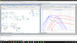
There is a 2 way mono crossover diagram. In the lower part, the output stage is responsible for generating a bass boost when turning the volume knob (like tone compensation)
The problem is that both channels are not synchronous. The HF channel is quieter with the same potentiometer position.
How can this be compensated and both channels synchronized?
Attached file for microcap


The problem is that both channels are not synchronous. The HF channel is quieter with the same potentiometer position.
How can this be compensated and both channels synchronized?
Attached file for microcap
Attachments
The first thing I would do is check your schematic.
Not a good idea to reference to the -ve rail!
Ensure the pots are linear or at least have the same type of resistance.
Not a good idea to reference to the -ve rail!
Ensure the pots are linear or at least have the same type of resistance.
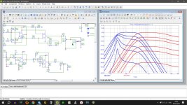
The potentiometers are identical in the simulator. The closer the knob is turned to 0 percent, the greater the discrepancy (about 5 decibels).
I am not sure if I got your issue completely. Assuming your schematic and assembly is fine.
Regular potentiometers don't track well together. So you may need to do this to mitigate the problem.
1. Spending sometimes to match the tracking of two pots and use matched pair. Time consuming. Inaccurate too unless it's a stepped one.
2. Spending some time building ladder potentiometer with low tolerance resistors.
3. Easiest and cheapest fix is to note the value of potentiometer position and resulting two resistance using a meter and replace with same value matched resistor divider on both channels.
With respect to mismatch between HF and LF levels you may need a series resistor or lpad to lower one of the louder driver.
You will also need to match almost every component values across stereo channels in your schematic.
The method above turned out to be inoperative. When adding a series resistor, the volume cannot be reduced to zero.
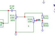
But fortunately I found another method that allows you to change the curve of the potentiometer adjustment by adding a constant resistor in parallel with one of the arms. This is resistor R42 in the diagram.
Resistor R40 simply imitates the input resistance of the amplifier.
But fortunately I found another method that allows you to change the curve of the potentiometer adjustment by adding a constant resistor in parallel with one of the arms. This is resistor R42 in the diagram.
Resistor R40 simply imitates the input resistance of the amplifier.
Attachments

- Home
- Design & Build
- Electronic Design
- How to match the volume of two channels