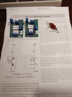
Attached is a picture of two little jigs I made up for matching mosfets as per Nelson Pass's article on matching mosfets. Don't mind that crazy looking resistor pack to one side. Nelson's article calls for a 56 ohm 2 watt resistor for testing vgs at 170mA. I didn't have such a resistor but I was able to parallel a bunch of other resistors from the 'spares' drawer to make up a 54.5 ohm resistor that's probably good for 5 watts.
The second photo shows the wiring arrangement (as per Nelson's article)
The connections are all identified to make it easy to use.
On the top right is the incoming DC Voltage with the plus on the top - marked V+
R1 allows for the insertion of various resistors for different voltages and mosfets.
VM is where you attached the probes from a multi-meter to measure the VGS
GDS just tells you which way to install the mosfet under test.
And I've labelled each for either P channel or N channel as the wiring is slightly different for each.
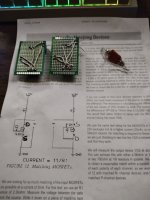
Attachments
Last edited: