Dear all,
I'd like to construct mu and White followers with lnd150's. Problem is that the specs vary between components, so I need to match them. however, I'm not sure how. can anyone explain how and what to match for the intended purpose of the mosfets? Kind regards.
I'd like to construct mu and White followers with lnd150's. Problem is that the specs vary between components, so I need to match them. however, I'm not sure how. can anyone explain how and what to match for the intended purpose of the mosfets? Kind regards.
The lack of help made me do my own research better. Here's what I did. Use a fresh 9V battery to set the drain through a 100 ohm resistor at 9V, while keeping the source and gate at 0V. This gave me a first reading of the Ids at Vg=0 so I could match. Next I used a 220 ohm drain resistor and measured again. Surprise: the Vg=0 matched mosfets matched again (now at roughly -250mV gate). In all cases I measured voltage drop over the drain resistor, which will lead to some errors. My fluke won't measure very small currents, so this was the best I could do for now.
Will they match the same way with 250V? I don't know. Need to build a far better test jig for that. Saturation/performance curves in the data sheets look very flat all the way to 500V, but you know 'paper is patient'.
Will they match the same way with 250V? I don't know. Need to build a far better test jig for that. Saturation/performance curves in the data sheets look very flat all the way to 500V, but you know 'paper is patient'.
You probably want to match for an "outcome" -- let's say 4 mA. You can use a potentiometer as Rset between source and ground, and perhaps a 150 ohm gatestopper between gate and ground. Connect the 9V to the drain and adjust the potentiometer until you get 4mA flowing through the circuit.
LND150 doesn't have a large SOA -- safe operating area -- i would use a DN2540,
Walt Jung has his "current sources' atricles from AX archived on his blog/website.
LND150 doesn't have a large SOA -- safe operating area -- i would use a DN2540,
Walt Jung has his "current sources' atricles from AX archived on his blog/website.
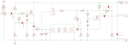
Take a look at the application I use the LND150 in. For more current there are indeed better choices I admit. But I don't expect the follower to drive much current at all. It will go to a delay effect with a 1 meg ohm input impedance. Guitar effects (stomp boxes that is) tend to be high input impedance.
A follower with a LND150 will drive a 10k load to 2V p-p just fine. Not for Hi-Fi of course, but we are talking guitar effects loop here.
I had to build the loop in a small Marshall amp, so it needed to be small in size (max 50x70 mm). No room for TO-220, current sources, mu-followers... Such a pity 😀
Attachments
- Status
- Not open for further replies.