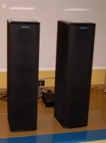
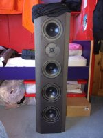
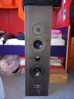
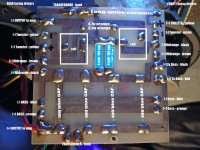
Hi guys, any ideas how I can make them into bi-wired ? The manufacturer did this just after I got these, so know its possible ! They are Musical Fidelity MC6 dipole floor-standers. Have taken them apart with Pano mediator from this forum watching over remotely from across the globe. Whilst inside I took the opportunity of identifying the wiring and took some readings. Please see attached pics. Thanks and hope you guys can shed some light.
Attachments
-
 MC6.jpg52.3 KB · Views: 352
 -
 IMG_20161003_164028.jpg414.8 KB · Views: 423
 -
 IMG_20161003_163934.jpg374.5 KB · Views: 333
 -
 IMG_20161003_013602.jpg432.3 KB · Views: 369
 -
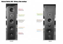 MC6 wiring diagram.jpg725.2 KB · Views: 350
 -
![MC6 Xover [front drivers on right]#3.jpg](/community/data/attachments/526/526904-3b2643c927add4d2489d976bd1b81f02.jpg?hash=OyZDySet1N) MC6 Xover [front drivers on right]#3.jpg579.6 KB · Views: 251
MC6 Xover [front drivers on right]#3.jpg579.6 KB · Views: 251 -
 Underside full layout.jpg881.5 KB · Views: 229
Last edited:
Hi to be honest not worth the hassle ,bi-wiring was another fad that many manufacturer's jumped on a few years back , the same manufacturer's that no longer make bi-wired speakers claiming no significant benefits.
No doubt there will be many that disagree with me and i'm not arguing just my personal opinion .
No doubt there will be many that disagree with me and i'm not arguing just my personal opinion .
Ok thanks, I should have pointed out that I wish to bi-amp using two stereo power amps.
Hi to be honest not worth the hassle ,bi-wiring was another fad that many manufacturer's jumped on a few years back , the same manufacturer's that no longer make bi-wired speakers claiming no significant benefits.
No doubt there will be many that disagree with me and i'm not arguing just my personal opinion .
Ok thanks, I should have pointed out that I wish to bi-amp using two stereo power amps.
well that's bi-amping, not bi-wiring.
I'm guessing the bits you have labelled "transformer" are inductors in the crossover network, to bi-amp you will need to decide which speakers you want to run off each amp and either hack up or re-build your crossovers.
ah I see, thanks, these speakers are a three-way design. Does one amp normally just drive the tweeters ? Three-way seems complicate things a bit then.
well that's bi-amping, not bi-wiring.
I'm guessing the bits you have labelled "transformer" are inductors in the crossover network, to bi-amp you will need to decide which speakers you want to run off each amp and either hack up or re-build your crossovers.
Follow the track that goes to the bass units you want to bi-amp and cut it before any crossover components, there you`d have to solder wire which connects to your new bi-wireable terminal (you`d need bi-wire terminals or add second pair of such). That`s it.
Bi-amping would have benefits if you`re using separate amplifiers. If its a receiver that has it as an option, its a marketing blurb most of the time - inside the receiver they`re wired in parallel so no benefit whatsoever. Bi-wiring (not bi-amping) as a concept is a pure product of reviews and manufacturers put it to please reviewers, not listeners.
Bi-amping would have benefits if you`re using separate amplifiers. If its a receiver that has it as an option, its a marketing blurb most of the time - inside the receiver they`re wired in parallel so no benefit whatsoever. Bi-wiring (not bi-amping) as a concept is a pure product of reviews and manufacturers put it to please reviewers, not listeners.
Thanks Mario, follow the tracks from the outputs ? They hit he coils immediately by looks of it.
Follow the track that goes to the bass units you want to bi-amp and cut it before any crossover components, there you`d have to solder wire which connects to your new bi-wireable terminal (you`d need bi-wire terminals or add second pair of such). That`s it.
Bi-amping would have benefits if you`re using separate amplifiers. If its a receiver that has it as an option, its a marketing blurb most of the time - inside the receiver they`re wired in parallel so no benefit whatsoever. Bi-wiring (not bi-amping) as a concept is a pure product of reviews and manufacturers put it to please reviewers, not listeners.
Attachments

I can see this ending in tears 🙂
Another thing not all will agree on is if you are using a passive x over bi -amping is a waste of time. For any perceived benefits you need active x overs .
Another thing not all will agree on is if you are using a passive x over bi -amping is a waste of time. For any perceived benefits you need active x overs .
Last edited:
Sorry, don't have active x-overs. Just rigging up these speakers to work with 2x stereo power amps will make more than happy 😉
I can see this ending in tears 🙂
Another thing not all will agree on is if you are using a passive x over bi -amping is a waste of time. For any perceived benefits you need active x overs .
Are the amps bridgeable? If so, will they handle your speaker's impedance? If yes, use each amp as a monoblock instead.
Sadly they are not bridgeable, got the pair so would be so nice to have both amp's channels doing their stuff.
Are the amps bridgeable? If so, will they handle your speaker's impedance? If yes, use each amp as a monoblock instead.
There would be some folks who'd suggest that upgrading the caps from NPE in a passive XO to even cheap Bennic poly films would offer an improvement in sonics, and while fully active bi or tri-amping is hard to argue against, even passive bi-amping can elicit at least improvements in dynamics and attainable SPLs, reduced distortion - albeit limited by the power available to drive the bass driver section. If using amps of different power levels, note their input sensitivities should be the same, or that some method of careful level matching should be available, otherwise one of the major functions of the passive XO may be over-ridden.
Bi-wiring from a single amp is a great way to sell more wire and audio jewelry connectors
Mario: note that some of the latest few generations of multichannel (i.e. Home theatre) receivers actually include the ability to provide true digital XO and bi-amping of front main speakers via the onboard DSP and assignment of amp channels not used for surround effects channels (usually front height or width) I have an Onkyo that does exactly that.
Last edited:
Hi Barbieboy,
In bi-amping you would probably want to separate the four woofers from the front and rear firing 2-way speakers.
Something does not look right about the connections that are visible in the solder-side picture of the printed circuit board for the crossover, has this been modified?
Anyway, you need to ring out the circuit, and draw a schematic before disconnecting the wiring (or cutting traces) for bi-amping.
Regards,
I think the simplest solution would be attempting to get hold of a set of x-over 's from the bi-wire version of those speakers ,assuming that no other changes were made all you would need to do then is fit a second set of terminals and you can bi-amp .
With out knowing exactly what you are doing if you make a mistake rebuilding the existing x-over 's at best nothing will work and at worst things are going to go bang.
Not intending any disrespect but from my own experience at times my enthusiasm far outweighs my ability and knowledge/understanding . There's only so much guidance people can give by looking at pictures . Before doing anything you need to know exactly what each part of the x-over does once thats done you can start splitting them into LF / HF sections .
It's going to be further complicated by the MF 's having so many drivers and not a simple two way design . What amps are you planning to use ?
As both the prior posts infer, the isolation of a "simple" multi-way parallel XO into its constituent band pass legs to allow for passive powering of each section can be relatively straightforward.
But it would certainly appear that this design is anything but (i.e. a 3 way bi-pole) , and short of obtaining a schematic of both this and bi-wire version of XO from the designer (rather than something reverse engineered by a DIY enthusiast) , any attempts to modify it would be fraught with grief at the very least.
But it would certainly appear that this design is anything but (i.e. a 3 way bi-pole) , and short of obtaining a schematic of both this and bi-wire version of XO from the designer (rather than something reverse engineered by a DIY enthusiast) , any attempts to modify it would be fraught with grief at the very least.
Interesting, so completely bypass the speakers internal x-overs. That would be a lot of speaker cables 😉
I have no idea if they have been tampered with, bought them second hand...
Hi Barbieboy,
In bi-amping you would probably want to separate the four woofers from the front and rear firing 2-way speakers.
Something does not look right about the connections that are visible in the solder-side picture of the printed circuit board for the crossover, has this been modified?
Anyway, you need to ring out the circuit, and draw a schematic before disconnecting the wiring (or cutting traces) for bi-amping.
Regards,
I have tried getting photos or any info from other owners without success. Really thought it wouldnt be so complex isolating the tweeters from the woofers before I opened them up 😕
I think the simplest solution would be attempting to get hold of a set of x-over 's from the bi-wire version of those speakers ,assuming that no other changes were made all you would need to do then is fit a second set of terminals and you can bi-amp .
With out knowing exactly what you are doing if you make a mistake rebuilding the existing x-over 's at best nothing will work and at worst things are going to go bang.
MF don't release anything about their equipment, I've tried on previous occasions 🙁
As both the prior posts infer, the isolation of a "simple" multi-way parallel XO into its constituent band pass legs to allow for passive powering of each section can be relatively straightforward.
But it would certainly appear that this design is anything but (i.e. a 3 way bi-pole) , and short of obtaining a schematic of both this and bi-wire version of XO from the designer (rather than something reverse engineered by a DIY enthusiast) , any attempts to modify it would be fraught with grief at the very least.
Barbieboy - as for completely bypassing the internal passive XOs, until such time as you know exactly what they might be doing besides simple band-passing, that's not a recipe for success either.
In other words, you might be best to just leave them alone, or do no more than upgrading the BPE (bipolar electrolytics) for low voltage poly film caps of equal value. Note that those types can be substantially physically larger than the BPEs.
In other words, you might be best to just leave them alone, or do no more than upgrading the BPE (bipolar electrolytics) for low voltage poly film caps of equal value. Note that those types can be substantially physically larger than the BPEs.
- Status
- Not open for further replies.
- Home
- Loudspeakers
- Multi-Way
- How to make my speakers bi-wire-able ?