Ok, I'm sure this can be done, I just don't have the electronics knowledge of how to go about this exactly. I thought it'd be neat if I could take some blue LEDs (which I have TONS in bulk), and some how wire them up so the brightness of them would be controlled in a sense by the volume of the music. And I could put them in places like behind the speaker grills, or in heater vents, places like that.
I figure I can feed off the signal just straight from the speakers, but not sure what I need to put together to convert that signal into something that controls the voltage going to the LEDs. Anybody know?
I figure I can feed off the signal just straight from the speakers, but not sure what I need to put together to convert that signal into something that controls the voltage going to the LEDs. Anybody know?

RE: LED
You could cheat and just hook it up to the supply in your amp. Kind of like a car stereo turned up really loud, and the headlights dim.
Then again, the music signal itself has a couple volts going on, doesn't it? Maybe a dc to dc converter to get it up a bit more. But I'm an accountant, not an electrical engineer 😀. So good luck, sounds like a project.
if that dosn't work out for you.. u can always get sum neon rod.. they have sum that are aleady built to syncronize to the beat of the music.. i have sum in my car.. and they wok great...😀
The national semiconductor LM3915 chip would be perfect for this, only problem is that you will need to do some soldering and thinking. Maybe you could get someone to help.
That was my first thought when I read his question, but actually it isn't. The LM3915 will power a number of leds depending on the input, not making them light up stonger/less strong.osey said:The national semiconductor LM3915 chip would be perfect for this, only problem is that you will need to do some soldering and thinking. Maybe you could get someone to help.
True I suppose, I was thinking of a VU type scale representing input when i posted that.
Thanks for the correction. Might still be worth investigating though if you have a lot of LEDs.
Thanks for the correction. Might still be worth investigating though if you have a lot of LEDs.
the LM 3915 is a log scaled device perfect for a VU setup where as the Lm 3914 is a linear device better suited for voltage/amperage displays....nice thing about them is they can be daisy chained to display a wider range than a single 10 output LED display
http://sound.westhost.com/project60.htm
I think Velleman has a VU kit as well.
You could always use different colored lights and array them so they don't obviously look like a VU meter.
I think Velleman has a VU kit as well.
You could always use different colored lights and array them so they don't obviously look like a VU meter.
Yeah, that would probably ok, but not really quite what I'm going for.
Another thing I was thinking of doing with this, is making these "angel eye" things. Where you take a clear acrylic rod, heat it and bend it to a ring. Then cut in many equally spaced notches all around it, and have some LEDs shine into it lengthwise in a gap in the ring. Then all of the notches light up, it looks REALLY neat!
And that only takes two LEDs, so the meter thing you guys are talking about really wouldn't work.
First of all I think that the ideea to hook up a resistor and the led in paralel with the speaker will work.I used it on one of my early amps.The led will glow at difrent intensities of the music.
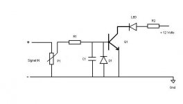
If you are not satisfied and want something more "professional" you could use some cheap transistors.Here is the schematic if intrested.
I used some BC 547. R1 is about 100 Ohms for a red led but I think that you should experiment a little.
On the input is a simple "low pass" filter.You can use what ever values you want (can't remember well but i think i used a 1k and a 1uF capacitor ).The diode I used was an old "Germanium dot-diode" (I don't know if this is the right term because i find it hard to translate) but I think you could use 1n4007.P1 is actually a trim-pot of 25K or 50k used for the input level and "sensitivity" of the schematic.
Try it at least for fun...
Attachments
Forgot to tell u something...
Instead of one led you could try to hook 2,3 up in parallel and change the value of R1.
Instead of one led you could try to hook 2,3 up in parallel and change the value of R1.
you don`t want to hook up LED`s in parallel with one resistor you need indivual resistors in series to each LED
R2 would be the series resistor for the LEDs, the collector current would then be divided across them.
I dont see a problem with using 2-3 in parallel.
I dont see a problem with using 2-3 in parallel.
gday
I have a box which i desingned specifically for this kind of thing. It runs on 12v and power HEAPS of LEDS in groups of 4. It works really well and i run 150LEDS and a light on it. Based on an old 30w amp. ANyway, Dick Smith Electronics have a kit that does this, it also has a built in microphone. www.dse.com.au
If anyone want my box yell out, i dont use it anymore.
Daniel
You guys are over complicating this. I have done this before, and it works very well. All you have to do is get a Bridge Rectifier, a few different resister values (one resister for each LED), and some capacitors, also varying in value.
1. Hook the AC inputs (~) on the rectifier up to your amp speaker wires in parallel.
2. Hook the DC outputs up to some wire leads. (Black to -, Red to +).
3.Hook the capacitor in series on the + wire.
4. Connect an LED and resister in parallel after the capacitor is wired into the + lead. Hook up the anode/cathode CORRECTLY, as reversing polarity might damage the LED.
5.Play music. Start at a low volume and see how the LED's are working. Depending on how you set it up, the LED's should not be lit up while the music is low, and gradually light up as you increase volume. ALSO, they will light up according to music transients i.e. when bass hits hard, they will be at their brightest.
6. I did not specify any capacitor/resistor values because you will want to vary them with your particular setup, and also because I do not know the formulas offhand...although it is a pretty basic one.
7.The resistor wired in parallel with the LED will limit the current going into the LED. Basically, it will keep the LED from burning up, which will happen if not implemented.
8. The capacitor wired in series is a high-pass filter. Depending on how large or small the capacitance, this will filter out low bass if desired.
9.You may want to use a potentiometer instead of resistors in that it will be easier to adjust the input sensitivity of your LED's. (i.e. adjust how brightly they light up according to your volume level).
10.Have fun!.
😀
If you have any questions, email me as I will try to help. I am not very precise with building these circuits, as they aren't too critical.
Sorry if this isn't enough information for you, I am only 17 and just getting started in this whole game.😉
use a voltage negative feedback summer amplifier(with adjustable gain, and dc input (optional) with a negative feedback amp(no gain) to return voltage to posistive, add pull up resistors (limit current) to your leds (all in parralell). audio in is 0-500mV, amplify it to .5 to 2V for the leds. can use as many as you want. 1 lm324 chip should work.
Just saw this thread and thought you might be interested. This site is Australian, but they ship to wherever and they have lots of other neat kits. This kit is for Neon lights, but I imagine it works for anything, just requires some solder knowledge to build I think.
http://www1.jaycar.com.au/productVi...&pageNumber=&priceMin=&priceMax=&SUBCATID=287
Hope that's helpful,
Butters
http://www1.jaycar.com.au/productVi...&pageNumber=&priceMin=&priceMax=&SUBCATID=287
Hope that's helpful,
Butters
- Status
- Not open for further replies.
- Home
- General Interest
- Car Audio
- how to make LEDs go to music?