Hello All
I like to reduce the inrush current on a large capacity linear PSU.
I have 2 x 3 68000µF at start i have put a chinise limiter (Carte de Protection de demarrage progressif, Circuit imprime haute puissance, Module de Protection contre le tonnerre de relais 220V 275V 100A | AliExpress) but the 10A fuse after the rectifier blown sometime again.
Can you help me?
Regards.
you do not put the fuse after the rectifier but before the transformer in series with the limiter.. If it is a 1000VA you take a slow blow 4 or 5A.
An externally hosted image should be here but it was not working when we last tested it.
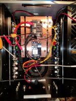
Here it was the PSU What kind of fuse i must use at the output of the PSU? Its for supply 2 Chinese copy KRELL KSA 100 MKII?
https://fr.aliexpress.com/item/1005001667256909.html?spm=a2g0o.cart.0.0.54833c001VxFFY&mp=1
Thanks for your help.
Regards.

Either use a thermistor NTC or use a soft start circuit using a relay and a resistor or thermistor.
Many years ago I designed a triac based soft start which worked very well but its a bit more complicated than a timed relay circuit.
Many years ago I designed a triac based soft start which worked very well but its a bit more complicated than a timed relay circuit.
Mongis, can you clarify what your original problem was (before you decided to use some form of inrush limiter), and provide some detail on what your circuit is ?
An externally hosted image should be here but it was not working when we last tested it.
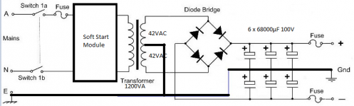
Here it was the schematic of the PSU the soft start was a chinise one.
Sorry, that link doesn't work for me.
Can you describe in more detail what your original problem was the power supply?
Can you describe in more detail what your original problem was the power supply?
Hello
I have some problems of blown fuses on the +/- Rails when it was put just after the rectifier my question was is it better in this configuration ? the Power aplifier was chines copy of KRELL KSA100 What kind of fuse i must put on the +/- Rails for supply the power amplifer boards?
I have some problems of blown fuses on the +/- Rails when it was put just after the rectifier my question was is it better in this configuration ? the Power aplifier was chines copy of KRELL KSA100 What kind of fuse i must put on the +/- Rails for supply the power amplifer boards?
It sounds like you are making up your own power supply, and have purchased parts - is that correct?
The schematic shows fuses between the caps and the amp modules. Why do you want to do it differently?
The schematic shows fuses between the caps and the amp modules. Why do you want to do it differently?
THe shematics display the NEW setup! Before i have put the fuses on +/- Rail Just after the rectifier. And some time i have blown fuse when i turn on the PSU (Fuses 10A) My question was is it better to do like on the schematic.
What kind of fuse i must use to put on the both raill for supply the 2 power boards a chinese copy of KRELL KSA100? Fast or Temporized Fuse and how much Amps?
Thanks for your help.
Here is it the setup:
What kind of fuse i must use to put on the both raill for supply the 2 power boards a chinese copy of KRELL KSA100? Fast or Temporized Fuse and how much Amps?
Thanks for your help.
Here is it the setup:
Attachments
I'd suggest you need to specify all the power supply parts, including transformer winding voltages and resistances, and the maximim continuous load current.
The Transformer was a 1200VA 2 x 42VAC at the secondary Primary was 230VAC the capacitys was a 6 x 68000µF 100V On the amplifer board i have not the current but it was a 80W class A amplifer very few information about it here the chiniese description of the boards:
This board refers to the KRELL KSA-MKII original circuit diagram, manual analysis of the line layout, integrated computer design, resulting in a very high performance ratio.
Works voltage: +/-DC30V-60V
0-AC12V (12-18V are alll ok) for speaker protection circuit.about 0.2A is enough
Output power: 80W +80W Class A Undistorted power
500W +500W Class AB. Undistorted power
( if you need the board works at Class AB. please send message to us. default are set at Pure class A)
Output impedance: 4-8 ohms
Board size: 385*115*45mm (W*L*H) include the Aluminum plate size
- Home
- Design & Build
- Construction Tips
- How to limit the inrush current on a very big linear PSU?