Is it the "good design line", or the "destructs after this" line? In other words, is it reasonable to design up to 90% of it, or should one design at, say, 50% of it?
Safe operating area sounds more like design, but I have a sneaking suspicion it's the destruction line.
Thanks,
Jeff.
Safe operating area sounds more like design, but I have a sneaking suspicion it's the destruction line.
Thanks,
Jeff.
At the collector voltage that your system runs the output transistor at, Andrew T used to tell us to use the DC soa rating for how much current a transistor could stand. Lots of popular transistors don't have a DC rating, only a 1 second rating.
When I look at commercial amps with 24/7 power ratings, that are very successful, I see they have done that. The max power rating determines the current the amp will put out on a non inductive resistor, and dividing by number of transistor pairs tells me what they were expecting out of the transistor. As Andrew used to tell us, real speakers sometimes take up twice the current of a non-inductive resistor.
For example look at Peavey Crown and QSC class AB products, which are very successful in a crowded market. You can get Peavey schematics without trying too hard, eserviceinfo.com comes to mind. Also here, but the search engine can't find anything. Loads up your results with the first word you typed in that comes up most recently.
Hint, Peavey 1990's products used MJ15024/25 most of the time. PV-4c, PV-8, PV-1.3k, CS800s, CS800x did. Those usually get huge dust balls on heat sink before blowing transistors, unless a 1/4 phone plug got pulled partially out & shorted the channel.
Last edited:
Audio magazine once did a test that showed up to five times more peak current into a loudspeaker load
than a resistive load, with a complex, asymmetrical test waveform. This is due to the reactive crossover
components not being in a steady state condition.
than a resistive load, with a complex, asymmetrical test waveform. This is due to the reactive crossover
components not being in a steady state condition.
Last edited:
Is it the "good design line", or the "destructs after this" line? In other words, is it reasonable to design up to 90% of it, or should one design at, say, 50% of it?
Safe operating area sounds more like design, but I have a sneaking suspicion it's the destruction line.
Thanks,
Jeff.
For safety consider it "instant destruction point" , 1 second and even more milliseconds count as "instant" in my book so design to never ever even approach it.
90%? ... *sounds* safe ... if you can guarantee not surpassing it which of course you can´t, speakers are crazy loads so stay well away.
Thanks, guys.
So in general I should stay well away from it, but for something like a CCS it sounds like one could push it to, say, 66% without undue worry.
Cheers,
Jeff.
So in general I should stay well away from it, but for something like a CCS it sounds like one could push it to, say, 66% without undue worry.
Cheers,
Jeff.
Yes stay away from it. And check the temperature for which that SOA graph is valid. Often it is at 25C. So when your amp has been operating for some time, the heatsink/junction is at a (much) higher temperature, and the SOA is a lot smaller.
Jan
Jan
Is it the "good design line", or the "destructs after this" line? In other words, is it reasonable to design up to 90% of it, or should one design at, say, 50% of it?
Safe operating area sounds more like design, but I have a sneaking suspicion it's the destruction line.
Thanks,
Jeff.
Think about it this way ... It's where you want your amp to be after 8 hours of flat out blasting music at a party.
the CCS at some NAP amplifiers gets hot. dissipation is (9ma/40V=360mw).... for something like a CCS it sounds like one could push it to, say, 66% without undue worry.
so barely 36%. going more than 40% would be risky.
me think.
Ron
Thanks, guys.
So in general I should stay well away from it, but for something like a CCS it sounds like one could push it to, say, 66% without undue worry.
Cheers,
Jeff.
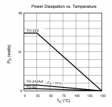
With a CCS if it has constant dissipation it's easier. Calculate the case operating temp that you expect and check the data sheet graph of allowed dissipation versus case temperature.
Attached for a DN2540.
Jan
Attachments
@robo7, I'd temp-derate the Zetex to about 800mW, which puts 360 at about 45%. Still, point taken that 66% may be pushing it.
Funny you should mention the NAP as the CCS that prompted this question is indeed a Zetex e-line part (although for a LTP rather than a VAS).
Cheers,
Jeff.
Funny you should mention the NAP as the CCS that prompted this question is indeed a Zetex e-line part (although for a LTP rather than a VAS).
Cheers,
Jeff.
Is it the "good design line", or the "destructs after this" line? In other words, is it reasonable to design up to 90% of it, or should one design at, say, 50% of it?
Safe operating area sounds more like design, but I have a sneaking suspicion it's the destruction line.
Thanks,
Jeff.
For secondary breakdown part of the line its a tipping point - pass the line and thermal-runaway will happen at an accelerating rate. Before you reach the 2nd-breakdown line the current hotspots are already developing, but not unstable. For the total power dissipation line cross the line and the die temperature will be rising to destruction in a linear way. For max voltage line the device will fail instantly at some point beyond it depending on luck and batch. For max current the bond-wires will act as slow-blow fuses I suspect.
Usually secondary breakdown is the limiting factor in output transistors, unless they are immune (lateral MOSFETs).
Most datasheets have lines for different pulse durations - the assumption is that its a low duty cycle pulsed waveform. For audio use I'd stick to the DC line, giving a small margin of safety, audio loads aren't low-duty cycle.
For secondary breakdown part of the line its a tipping point - pass the line and thermal-runaway will happen at an accelerating rate. Before you reach the 2nd-breakdown line the current hotspots are already developing, but not unstable. For the total power dissipation line cross the line and the die temperature will be rising to destruction in a linear way. For max voltage line the device will fail instantly at some point beyond it depending on luck and batch. For max current the bond-wires will act as slow-blow fuses I suspect.
Thanks, Mark.
Speaking of max voltage, I recently ran some tests on a batch of BC239Cs for use with 40V rails. About 1/3 of them avalanched just north of 50V, about 1/3 between 50V and 80V, and the remaining 1/3 still hadn't avalanched when I stopped at 85V.
I'm under the impression that a couple of seconds of avalanche won't do them any harm, and that I could use the top half of them (which made it well past the rail voltage). Is that correct, or should I only be using the ones that didn't avalanche? (i.e.: did avalanching do them harm?)
Thanks,
Jeff.
FWIW the BC239 is rated for only 25V -- a spec which would appear to be wildly conservative.
Normally if a device avalanches its suddenly dissipating lots more power than its rated for (assuming its a power device and accidentally exceeding its voltage rating) Avalanche within max dissipation limit can cause direct damage though, due to current crowding effects, if I remember right (bit like a another kind of 2ndary breakdown)
If the current at avalanche is limited to a safe dissipation, there should be no damage. A zener diode is constantly avalanching - it's it's purpose in life.
Jan
Jan
I'm under the impression that a couple of seconds of avalanche won't do them any harm, and that I could use the top half of them (which made it well past the rail voltage). Is that correct, or should I only be using the ones that didn't avalanche? (i.e.: did avalanching do them harm?)
Thanks,
Jeff.
FWIW the BC239 is rated for only 25V -- a spec which would appear to be wildly conservative.
They might only be able to handle significant current at 25V. Don’t assume it will b able to handle full dissipation at 40V. They used to do this selecting 2N3055s for use at more than +/-30V. It might avalanche at 200V, but only be good for 20mA at 100V due to second breakdown. In addition to your rough Vceo test, you may also want to test several at your desired operating current and voltage just to make sure. Set it up as a current source, and see if it takes it. If it blows or runs away you have t really lost anything - you couldn’t have used it in your circuit anyway.
If the current at avalanche is limited to a safe dissipation, there should be no damage. A zener diode is constantly avalanching - it's it's purpose in life.
Jan
A true zener diode uses quantum-tunneling, high voltage "zener"s are avalanche diodes, many have both effects in play. They are devices designed to handle sustained avalanche, and things like current crowding are designed out or managed.
A big power device in avalanche can fail because the avalanche current concentrates in hot-spots and melts those parts of the chip before the nominal dissipation limit. In a severe avalanche charge-carriers gain enough energy to disrupt the lattice, not just ionize individual atoms. Its the same process as when insulators breakdown under very high electric fields.
Electromigration is another possible result of sustained avalanche that can cause long term damage.
A big power device in avalanche can fail because the avalanche current concentrates in hot-spots and melts those parts of the chip before the nominal dissipation limit.
That’s called secondary breakdown. It just happens to be happening at zero bias, as opposed to the usual forward or reverse. It will likely follow the FBSOA curve, because it really IS forward biased, with Icbo. In some big power devices, especially ones designed for switching, the Ic limit at rated Vceo may not be much more than the spec Iceo. Sometimes just a handful of watts.
Electromigration is a function of current density. Jc can be quite large in a hot spot, that’s why it’s hot.
They might only be able to handle significant current at 25V. Don’t assume it will b able to handle full dissipation at 40V. They used to do this selecting 2N3055s for use at more than +/-30V. It might avalanche at 200V, but only be good for 20mA at 100V due to second breakdown. In addition to your rough Vceo test, you may also want to test several at your desired operating current and voltage just to make sure. Set it up as a current source, and see if it takes it. If it blows or runs away you have t really lost anything - you couldn’t have used it in your circuit anyway.
Cool; I'll file that for future reference. In this particular case they're barely ticking over at 0.6mA.
Cheers,
Jeff.
- Home
- Amplifiers
- Solid State
- How to interpret the SOA line?