Hi all,
I'm building a tube buffer output stage to go in my modded Marantz CD63 CDP and because of the size limitations, I can't use a pre-made PCB like an Aikido Cathode Follower, although that's basically what I need. So I need to make a custom board, which I'm kind of cool with in principle, but have never done before...
I've done my research and viewed a few tutorials and such and I like the KiCAD software for the ease of use, functionality and the fact it's nice and free, but I'm baffled at how to include a dual triode tube like an ECC82 in the schematic.
I've tried with the standard library valves and also imported an additional library of valves, but they all seem to drop-in as single triodes and I don't understand how to tell KiCAD that they're part of the same physical envelope.
Has anyone here done that before who could offer a couple of basic pointers please?
thanks in advance,
James
Hi all,
I'm building a tube buffer output stage to go in my modded Marantz CD63 CDP and because of the size limitations, I can't use a pre-made PCB like an Aikido Cathode Follower, although that's basically what I need. So I need to make a custom board,...
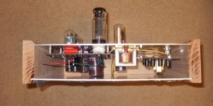
A PCB for a tube amp? That was just a production shortcut. If you are building just one amp for yourself you can use point to point connections or if you like a "turret board." The Turret board was the way all high end stuff (e.i. non-consumer) was build before PCBs It is likely the best compromise.
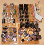
Google will turn up all kinds of info but there is a photo of a tube based reverb I built using turrets, It was the technology of choice in the 1950s and still is the best today. It is to expensive for high volume production work but ideal for one-off amps. Better then point to point because it is easy to modify
https://www.dropbox.com/sh/apxv6bo80gkg63v/uNe3VoXBUO/guts%20angle%20view.jpg
More here:
Turret board - Wikipedia, the free encyclopedia
and here is one more example. If you lke you can mount a tube socket to the board but most peole like to mount the sockets to the metal cassis.
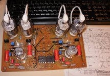
http://www.turretboards.com/images/PRODUCT/boards/loaded_fender_champ_vibro.jpg
Last edited:
A PCB for a tube amp? That was just a production shortcut. If you are building just one amp for yourself you can use point to point connections or if you like a "turret board." The Turret board was the way all high end stuff (e.i. non-consumer) was build before PCBs It is likely the best compromise.
Google will turn up all kinds of info but there is a photo of a tube based reverb I built using turrets, It was the technology of choice in the 1950s and still is the best today. It is to expensive for high volume production work but ideal for one-off amps. Better then point to point because it is easy to modify
https://www.dropbox.com/sh/apxv6bo80gkg63v/uNe3VoXBUO/guts%20angle%20view.jpg
More here:
Turret board - Wikipedia, the free encyclopedia
and here is one more example. If you lke you can mount a tube socket to the board but most peole like to mount the sockets to the metal cassis.
http://www.turretboards.com/images/PRODUCT/boards/loaded_fender_champ_vibro.jpg
Thanks Chris,
possibly, I've posted in a slightly confusing section, but this looked to be the best/only place for my tube/vale query..
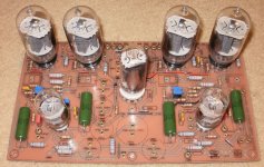
I currently have an SRPP Valve output stage in my CD player using a custom PCB which someone else made.
It's this schematic:
An externally hosted image should be here but it was not working when we last tested it.
to make this board
An externally hosted image should be here but it was not working when we last tested it.
which fitted neatly up the side of the cd player thusly:

That was taking it's input signal direct from one pair of the DAC's output, which was nice, but not correct as this DAC uses a differential output which needs to be summed together properly.
I've now done a load of modifications to the CD player, but significantly I'm now using a Discrete Output Stage to sum the outputs correctly, then going out via the valve stage, but this is now giving me far too much gain.
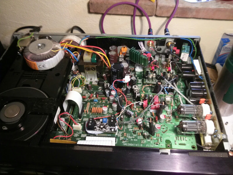
Here's a picture of the busy mess I now have 🙂
So I want to change the tube SRPP stage to a tube buffer, ideally using somethign like the Aikido Cathode Follower circuit.
An externally hosted image should be here but it was not working when we last tested it.
I was looking for a custom PCB because:
1) The ACF board is 4" x 6" so won't fit where I want (I have maybe 2.5" x 8" space)
2) A custom PCB would be compact and would avoid a further jungle of wires.
3) I have access to an etching bath.
4) A good software package would help me juggle the routing and placement of the components in a way which I would struggle to do as quickly or effectively on paper.
cheers,
James
I happen to like PCB's + tubes. Just for the cleanliness and fun of making a PCB! A properly designed PCB performs just as well as point-to-point wiring.
I've never used KiCAD, but use Eagle a lot. There are a ton of libraries, including some for tubes. Depending on the tube sockets you're using, you might have to adjust or remake the PCB footprints, but that's pretty easy in Eagle. Plenty of YouTube tuts.
Concerning the triodes in the same envelope, every PCB package I came across had the ability to select different parts within a single housing/envelope/package. Wether it's an quad opamp or a triode. I know this for a fact for Eagle (even lets you place the heater somewhere else in the schematic, for clean PSU schematics).
I support PCBs for tube circuits as well. They're much easier to reproduce and provide consistent performance. It's also much easier to optimize a board for signal integrity than it would be to optimize a wiring harness. But hey... Each to their own.
I have no experience with KiCAD, but in the CAD programs I've used, there's been a way to define a homogeneous part - i.e. a part with multiple similar subcircuits inside. Many logic ICs are defined this way. For parts that contain multiple different subcircuits - like compactons - you can define a heterogeneous part.
~Tom
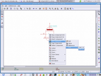
Perfect, thanks 🙂Right click on component. In drop down menu select "Edit Component" > "Unit"
PCB's, Sand mix well with Glass. It must be done with cross coupling and parasitics in mind on all traces, just like wire routing in a P-P. Heat management / dissipation must be involved in the design and implementation into a chassis. You can do etch in a ziploc bag, toner transfer etch resist. All PCB's were done this way. For feed thoughts I used Brass eyelets, wire attach points and to mount caps to the back side.
I've seen bad PCB designs and bad P-P wiring, Good PCB's and P-P designs just take longer and more effort in the planning stage.
I've seen bad PCB designs and bad P-P wiring, Good PCB's and P-P designs just take longer and more effort in the planning stage.
Attachments
- Status
- Not open for further replies.
- Home
- Amplifiers
- Tubes / Valves
- How to include a dual triode tube in a KiCAD schematic?