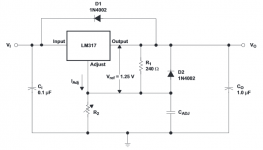
I am building a voltage regulator circuit for powering a pair of mini-speakers (about 3-5W) with built in amplifier and an old mp3-player/FM radio. The power source is an old mobile phone charger (an unregulated switching PSU, nominally 5V at 350mA, however provides 6.7V when measured at max volume, because the load is small), this input voltage is regulated to 4.2V by the LM317 (Both devices were originally powered by 3.7 Li-ion batteries). I use a circuit based on this one found in the datasheet:
Cadj is 10uF. The circuit works OK, noise levels are low. However, using an oscilloscope in AC coupling mode and playing back music, I see a significant variation in voltage that follows the audio signal’s transients. A kickdrum can drop the voltage by around 0.5V (i.e. about 12% of Vs) and I measure peak-to-peak voltages of around 1V (24% of Vs). Adding a 1000uF electrolytic cap on the input side in parallel with Ci reduced the max peak-to-peak voltage swing to about 250 mV. Subjectively, the basses sound fuller and deeper with the large capacitor.
My questions are the following:
1. What would be acceptable levels of voltage variation due to transients in a (consumer level, low power, i.e. not hi-end) audio application? How exactly do these transient voltage drops affect the sound?
3. What is the correct approach to reduce these V swings? Do I also need to add a larger cap on the output? (in parallel with Co in the above circuit diagram)? What capacitance value would you recommend for the input, output and Cadj? I am aware of the issue that high ESR caps are preferred on the output, so what would be the highest acceptable capacitance of the output cap (if any)?
An externally hosted image should be here but it was not working when we last tested it.
Cadj is 10uF. The circuit works OK, noise levels are low. However, using an oscilloscope in AC coupling mode and playing back music, I see a significant variation in voltage that follows the audio signal’s transients. A kickdrum can drop the voltage by around 0.5V (i.e. about 12% of Vs) and I measure peak-to-peak voltages of around 1V (24% of Vs). Adding a 1000uF electrolytic cap on the input side in parallel with Ci reduced the max peak-to-peak voltage swing to about 250 mV. Subjectively, the basses sound fuller and deeper with the large capacitor.
My questions are the following:
1. What would be acceptable levels of voltage variation due to transients in a (consumer level, low power, i.e. not hi-end) audio application? How exactly do these transient voltage drops affect the sound?
3. What is the correct approach to reduce these V swings? Do I also need to add a larger cap on the output? (in parallel with Co in the above circuit diagram)? What capacitance value would you recommend for the input, output and Cadj? I am aware of the issue that high ESR caps are preferred on the output, so what would be the highest acceptable capacitance of the output cap (if any)?
Attachments
Have you checked what is happening on the input side of the voltage reg? ie is it staying at a constant 6.7V or is it dropping as well. The fact that adding a 1000uF cap on the input side helped seems to suggest that the actual power supply is not able to handle the current demanded on transients and is reducing in output possibly to a lower voltage than the drop out voltage of the regulator.
Tony.
Tony.
I did not look at the input side with a scope, however I measured 6.7V with a multimeter under maximum load, i.e. while playing music on full volume. The no-load voltage on the PSU is 7.38V, while the nominal V is 5V@350mA. I did test the PSU up to 300mA with static loads and it performed allright. Tomorrow I'll check the input side voltage with a scope and test the regulator with another PSU. It is possible that the transients make the V of the PSU drop temporarily below 6.7, and it can't provide the 4.2+2.5 = 6.7V necessary for maintaining the 4.2V output voltage. Would a large capacitor help in this case, or should I rather use a PSU with a higher voltage rating? I could also lower the output voltage to 3.8-4.0V.
Last edited:
Looks pretty bad, doesn't it? I always place a passive follower AFTER the regular for each gain block. Fixes the transient problem, lowers the noise.
Regardless of the acutal cause of this problem, what capacitor values would you recommend on the input and output of an LM317 regulator circuit for powering a small amp? I've seen some different values in this thread:
http://www.diyaudio.com/forums/power-supplies/268484-where-put-largest-capacitor-2.html
What I gather from this thread is this:
- Large input cap (1000uF or above)
- Medium sized output cap (around 100 uF) altough some people use even larger (1000 uF) with a small series resistance to increase ESR. Also, high ESR is important for the output cap.
- Relatively large (more than 10 uF) Cadj reduces noise
In what different ways do the input and output caps affect the circuit? Should I also keep the 1uF cap on the output besides a larger (100 uF) one, or is it unnecesary in that case?
I'd look for a slightly higher voltage transformer or PSU. The LM317 does not perform ideally until there is roughly 3.5V across it, and ideally this should be the case even at low line under load. Make sure you have sufficient heat sinking to dissipate the heat under full load.
Note that the sampling rate of your multimeter is likely not high enough to catch the voltage drops on transients. You will be seeing an average value. I would put the scope on the input side and see what is happening before doing too much.
+1 for the 3.5V in to out differential too.
edit: too big a cap on the output (especially a low ESR one) can affect the stability. The output of the LM317 has some inductance, and the cap if low enough ESR will interact with it and resonate. You probably want at least 0.5 ohms of resistance (iether via esr or added) to damp any resonance if you go with a big cap.
Tony.
Besides what everyone else has advised (get the raw supply right!), I'd recommend a close read of Erroll Dietz's article on the 317. It was reprinted as an appendix to Bob Pease's superb little book. Bottom line: big output cap, moderately big adjust cap, higher current (preload if you need to). This minimizes output impedance and noise.
http://www.pearl-hifi.com/06_Lit_Ar...Pease_Bob/Troubleshooting_Analog_Circuits.pdf (see Appendix C)
http://www.pearl-hifi.com/06_Lit_Ar...Pease_Bob/Troubleshooting_Analog_Circuits.pdf (see Appendix C)

If I may add my € 0.02, an often overlooked factor is where you measure. The LM317 can only regulate what it sees. The right way to measure is between the LM317 output pin and the bottom of the resistor on the adjust pin. I would expect the variation to be much less (unless the input voltage causes drop-out of course). If at the direct points the variation is not there, you have an issue with wiring and/or grounding.
Jan
Jan
Thanks for the useful input. I checked the input on the scope as suggested, and indeed, the PSU feeding the regulator dropped it's voltage to as low as 6.1V on some transients. Since I need an output of 4.2V, the overhead was only 1.9V which caused (a siginificant part of) the problem. I also tested with a large oldschool wallwart PSU which did not drop below 7.5V not even on transients, and the transient response improved significantly from 2-500 mV to about 70-90 mV (from 12% to 2%). Subjectively I did not notice too much difference in the sound, maybe the bass is more punchy and fuller, but consider that these are very small speakers (2 inch cubes) made for mobile phones, so while they sound good for their size, they are too small to amplifiy anything to very noticeable levels. I will have to find a more powerful mobile charger though. Obviously they are not designed for transient loads, but I have a dozen lying around along with a bunch of LM317s.
Regarding caps: I've tested putting various capacitors on the input: 470uF, 1000uF, 2200uF and 2x2200uF. Again, subjectively there is not much difference, while on the scope the 4400uF vs 1000uF reduced peak-to-peak transient voltages by about 25%.
Regarding caps: I've tested putting various capacitors on the input: 470uF, 1000uF, 2200uF and 2x2200uF. Again, subjectively there is not much difference, while on the scope the 4400uF vs 1000uF reduced peak-to-peak transient voltages by about 25%.
- Status
- Not open for further replies.
- Home
- Amplifiers
- Power Supplies
- How to improve transient load response of an LM317 voltage regulator circuit?