H all,
I obtained some 6AV6 and 6AQ5, along with a couple of Altronics M1120 transformers:
Cheap Output Transformers
to use as output transformers (Somebody worked out these suit 6V6 at about 8K impedance). Now I know I could use different (better) valves and transformers, but the fun is to try and use these to make an acceptable stereo amp. I found this schematic:
http://pacifictv.ca/schematics/electrohomehft400-6watt.pdf
which I am using except substituting a pair of 6AV6's for the splitter. I have built one channel on the bench and have semi-reasonable sound from the speakers, albeit it takes most of an iPod output to drive it. I had to add a cap from the anode of the top 6AV6 to ground to kill a 248Khz oscillation, and I only had 3 x 472 caps in series on hand to try. Bass seems reasonable, but it seems to lack top end frequencies and "clarity" (don't know how else to describe it). I assume the cap I added is too large, and will pick up a 220 or 470pF to put in.
I intend on the weekend to try to characterise the frequency response and see how it s actually performing. Will post if I am successful.
Are there any improvements anybody can offer to make this a nice little amp for a small room?
Thanks,
Glenn.
Last edited:
There is a hint in the "iron" link as to why you should avoid them. Notice the remark about lack of heft. That equates to poor magnetic headroom and the cores will saturate from the deep bass error correction signal associated with the global negative feedback (GNFB) loop. The warning about overheating is also telling. TANSTAAFL!
As for the schematic, the 470 Kohm I/P resistance will interact adversely with the high Miller capacitance of the 12AX7/ECC83 triode to roll high freq. info. off. The paraphase topology shown is out of favor, for legitimate technical reasons. Find another setup that uses either a "concertina" phase splitter or differential, AKA long tailed pair (LTP), phase splitter.
As for the schematic, the 470 Kohm I/P resistance will interact adversely with the high Miller capacitance of the 12AX7/ECC83 triode to roll high freq. info. off. The paraphase topology shown is out of favor, for legitimate technical reasons. Find another setup that uses either a "concertina" phase splitter or differential, AKA long tailed pair (LTP), phase splitter.
Thank you @Eli Duttman.
I am not expecting much power out of these, so overheating is unlikely to be a problem, but GNFB.... maybe.
The second paragraph is EXACTLY the kind of advice I was after. I have the transformers, and if I can improve the electronic design to where I out-strip the transformer design, I will be happy. Down the track I can maybe swap out the transformers with better ones.
Don't get me wrong, I have just completed a pair of Bruce Herran's Oddwatt amplifiers using Edcor iron so I know what quality should be, and I am almost finished a pair of Frugel Horn XL speakers to complement them. These are for fun and on a serious budget after all the previous expense.
I tripped across a long tailed pair with CCS earlier today, maybe I can find that design again and implement it. 🙂
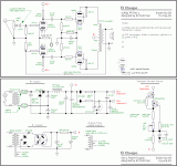
Since you mentioned LTP plus CCS, I'll provide a design I'm associated with, "El Cheapo". The schematic shows triode wired "finals" and that is definitely the thing to do with marginal O/P "iron". Power O/P will be approx. 6 WPC.
As you seem to like inexpensive 7 pin mini single triodes, the 6AB4 is the type to use as a substitute for the 12AT7/ECC81
As you seem to like inexpensive 7 pin mini single triodes, the 6AB4 is the type to use as a substitute for the 12AT7/ECC81
Attachments
Ok. I found the howlermonkey version 1
The Howler Monkey Push Pull 6AQ5 Guitar Amp
and substituted the phase inverter circuit in my schematic. Now I have fantastic high but I have lost my bass. Obviously my output is ok, and transformer can provide the bass. What in the phase splitter circuit is frequency altering? I did some research, but failed to grasp the problem and possible solution.
Thanks,
Glenn.
There is a hint in the "iron" link as to why you should avoid them. Notice the remark about lack of heft. That equates to poor magnetic headroom and the cores will saturate from the deep bass error correction signal associated with the global negative feedback (GNFB) loop.
Negative feedback is not causal of the output transformer limitation. The power is 99.9% or more going to the speaker, not the feedback network. The lack of enough mutual inductance of a small transformer is what leads to saturation at low frequencies / high voltages - this happens with or without load, but leakage inductance will increase the saturation at higher load currents.
With low mutual inductance the magnetizing current will be larger and transformer efficiency will drop off towards the low end even if saturation isn't an issue.
Note that global feedback can compensate for deficiencies of the transformer (LF and HF response drop-off, mild saturation effects), staving off the worst effects upto a point - but ultimately there is a saturation limit and hitting that will provoke lots of distortion, intermodulation, overload the output stage and generally be horrid. And yes at this point the output stage will be mainly generating error signal to compensate for the transformer, but this is a result of transformer saturation, not the cause of it.
Ok, so I unplugged the output tubes and put in 1Khz sine wave. Scope on the iutputs and the non-driven valve has well under half the output of the driven side. I also did some frequency /gain measurements and it is just like it sounds, 2.3V P-P at 300 Hz, 6.8V at 1Khz, 10V at 2Khz. 15V at 10Khz.
So at this point I have to discount the outputs and transformers. both 6AV6 have 1mA each and 227 on the Anodes. 13V on the cathodes, 9,75 on the non-driven tube and 11.2 on the driven tube screen.
Can anybody help me decipher those numbers?
So at this point I have to discount the outputs and transformers. both 6AV6 have 1mA each and 227 on the Anodes. 13V on the cathodes, 9,75 on the non-driven tube and 11.2 on the driven tube screen.
Can anybody help me decipher those numbers?
Attachments
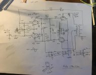
Update. I changed the LM317 resistor to 910 ohms, which should calculate to 1mA according to online calculator. I now have a symmetrical waveform at least and twice the P-P voltage at 1Khz, so heading the right direction at least.
Ok, changing the 470k screen resistors to 680K gives me much more bass and output. Can somebody please explain the theory to me?
Last edited:
This actually sounds pretty good now. Added 220K resistor feeding the LPT so it now has 100 volts on the Anodes and the sound has not suffered in the least (to my ear anyway). At low volumes there is a lack of bass, but when you turn it up to reasonable levels, for a cheap transformer it sounds pretty good.
I have a weird problem though. I run through my variac as of norm when I am playing and it sounds great with it set to be identical to the incoming mains. When I move it to be plugged directly into the mains, I get a burbling distortion through the audio. So what might be in a variac (auto-transformer) that might make a difference? Extra inductance on the primary? Maybe some caps on the variac for protection? My variac will do about 10% over, so I thought initially I had too much voltage but carefully setting it and there is no difference. Grounding maybe?
I have a weird problem though. I run through my variac as of norm when I am playing and it sounds great with it set to be identical to the incoming mains. When I move it to be plugged directly into the mains, I get a burbling distortion through the audio. So what might be in a variac (auto-transformer) that might make a difference? Extra inductance on the primary? Maybe some caps on the variac for protection? My variac will do about 10% over, so I thought initially I had too much voltage but carefully setting it and there is no difference. Grounding maybe?
I do not get the nfb , whatever is coming from the OT will be injected to both sides
of the phase inverter. What is the theory behind this ?
of the phase inverter. What is the theory behind this ?
I am by no means an expert, but I believe that this is global negative feedback. The feedback from the output transformer is out of phase with the normal input, so results in less gain. The theory is that the audio from the transformer is distorted as it goes through and what gets fed back is the distorted signal. That tends to cancel out the distortion and helps make up for the poor iron.
Please do correct me if my understanding is wrong, or maybe my circuit is wrong. It doesn't seem to make a huge difference when I disconnect the feedback loop I must admit.
Cheers,
Glenn
Please do correct me if my understanding is wrong, or maybe my circuit is wrong. It doesn't seem to make a huge difference when I disconnect the feedback loop I must admit.
Cheers,
Glenn
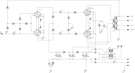
Looks like a cap is needed from the NFB at R14 to the VT1 grid. You may not hear much with N Fdbk applied with such small output tubes though.
Do the tube heaters each have 6.3V across them, hard to tell from the labeling.
6AS6 are tiny dual control RF pentodes, with very compressed output unless you put around +8V to +10V on grid 3 with respect to cathode. I thought you mentioned 6AQ5 tubes as available. Use the 6AS6 tubes for fishing bobbers. Even sub-mini wire leaded tubes can leave 6AS6 in the dust.
Last edited:
You are quite correct, the output valves are 6AQ5, I just used that symbol in Eagle and forgot to change it. I'll try the cap next time I get to play. Thanks for that.
Oh, and the heaters are fed 12 volts, two heaters in series.
Oh, and the heaters are fed 12 volts, two heaters in series.
OK, much better!
-----------------------------
Around 1/2 NFB to the tail, as well as full NFB to the other grid1, makes the tail resistor look like a CCS. Clever old designs. Not sure if it is implemented fully correctly here. Maybe RDH4 has some section on this.
-----------------------------
What is the theory behind this ?
Around 1/2 NFB to the tail, as well as full NFB to the other grid1, makes the tail resistor look like a CCS. Clever old designs. Not sure if it is implemented fully correctly here. Maybe RDH4 has some section on this.
Last edited:
- Home
- Amplifiers
- Tubes / Valves
- How to improve this circuit for stereo audio amp 6AV6/6AQ5