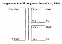
I don't understand the question. There is the secondary voltage between the two ends Usek and 0. Since the secondary voltage swaps polarity 50 times per second (or 60 times in North America), there's no 'start' or 'end'.
The reason why the ends are labelled is to know how you would need to connect them for series operation. Connect the 0V of the top one to Usek of the bottom one and they are in series, with the two connected points as center tap.
But the naming itself is arbitrary; I could easily name them 'somewhere' and 'somewhere else' with no consequences, as long as both secondaries were correctly named related to each other.
Very often you see that a dot is placed near one wire of a secondary. That's another way to say that you need to connect the 'non-dot' of one to the 'dot' of the other for series/center tap operation. If you would connect the two dots (or the two Usec's) there would be zero voltage end-to-end because they would be in opposite phase and cancel each other.
Jan
Sorry for my English.I don't understand the question.
Jan
I need to know the beginning of the winding (there is a beginning and an end), how in this case is this denoted?
In the standard case put a point when the winding begins.
thanks for the help.
Attachments
Sorry if I wasn't clear enough before.
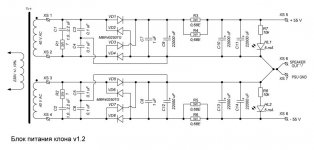
Just put a dot at the Usec end for both secondaries, XS1 and XS3. Since you use the two windings separately, it doesn't make any difference anyway. Only if you use a center tap they must be in series.
BTW Why use two complete rectifiers and capacitors? Grounding the center tap and using a full wave rectifier is simpler with less parts.
Jan
Last edited:
Hello all,
A successful operation: a thermistor is placed between fuse and xformer's primary.
Tested the T1.6A (and even a T1.25A) fuses several times at short intervals, they didn't blow.
Thermistor didn't get hot or even warmer (rated at 8.5A). No AC voltage drop at secondaries.
Thank you all.
A successful operation: a thermistor is placed between fuse and xformer's primary.
Tested the T1.6A (and even a T1.25A) fuses several times at short intervals, they didn't blow.
Thermistor didn't get hot or even warmer (rated at 8.5A). No AC voltage drop at secondaries.
Thank you all.
Last edited:
Google ПереводчикBTW Why use two complete rectifiers and capacitors?
Jan
If it had no effect, it would not have been indicated by the developers.Then other people will not be confused by trying to find the 'start' when it has no consequence.
Nothing there I see that discusses why two separate supplies would be preferred over a full wave system.
If it had no effect, it would not have been indicated by the developers.
You misunderstood him. He was meaning that the people who put on those dots should make clear when they would not make any difference, as in your case.
But I don't agree to that; I think that a developer of a transformer might reasonably expect the user to understand the importance (or not) of those dots. Expecting some basic understanding is not unreasonable.
Jan
Last edited:
He was meaning that the people who put on those dots should make clear when they would not make any difference, as in your case.
Jan
 I was not given to understand this, it raises questions. If the engineer pointed to the beginning of the transformer winding, then this is the law!
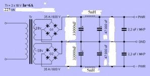
Please tell me the percentage of ripple at the output of the power supply, with nominal values stated in the scheme.
Attachments
Last edited:
No. Sometimes a dot appears when it has no relevance, perhaps because a standard library drawing of a transformer includes it? Draughtsmen preparing official copies of circuit diagrams do not necessarily understand electronics. Unnecessary information can sometimes be as confusing as missing information. This thread exhibits this.LongRoad said:If it had no effect, it would not have been indicated by the developers.
- Status
- This old topic is closed. If you want to reopen this topic, contact a moderator using the "Report Post" button.
- Home
- Amplifiers
- Power Supplies
- How to identify the "phase" between the two white wires at this primary