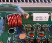
Hi, I have my PCB and right now I soldered a lead from one of my common ground v0 to the chassis.
Is there a way to design the PCB with a via/hole attached to the ground plane and then use a metal screw or some kind of post that screws in to the ground of the PCB and then run a wire to a ground post to the chassis?
Is there a way to design the PCB with a via/hole attached to the ground plane and then use a metal screw or some kind of post that screws in to the ground of the PCB and then run a wire to a ground post to the chassis?
Last edited:
Yes, a large single through-hole can be defined as a component(*). Use a crinkle washer on the post. If the post itself screws to the chassis you have local grounding. For local star-grounding on the pcb you should run individual ground traces from a single such grounding point around the PCB.
However if you wish to stick to strict star-grounding throughout you'll probably need to run wires from the single chassis star-grounding point to all the relevant PCBs.
(*) Normally a drill hole will exclude traces nearby, so you need a large through-hole pad.
However if you wish to stick to strict star-grounding throughout you'll probably need to run wires from the single chassis star-grounding point to all the relevant PCBs.
(*) Normally a drill hole will exclude traces nearby, so you need a large through-hole pad.
My PCB is a full ground plane. I.e I have a full copper pour layer.
So if I use a large through hole and assign it to the ground plane with proper copper spacing and screw a post into it I should be fine? Is there a "standard" size?
So if I use a large through hole and assign it to the ground plane with proper copper spacing and screw a post into it I should be fine? Is there a "standard" size?
