I've built a few SE amplifiers using 300b/6B4G on multiple chassis - easier to experiment with and it splits up the weight of a single chassis. A friend is interested in having such an amp but he has very efficient speakers, while mine are around 87db. So I'll have to address the issue of hum. I don't have a scope set up so no way to measure the hum effectively. So I'd like to follow your best advice in wiring up the grounds.
The elements are:
1. HT supply
2. Filament supply for 300b/6B4G. This will be DC using 50VA transformers.
3. Signal circuit output stage and indirectly heated triode input stage. These will go together. The input stage will need DC heaters, but that's simple.
So possible splits:
1. HT and output filament supply in separate chassis. Signal chassis for the rest
2. HT and signal circuit in one chassis, filament supply in a separate chassis. I do this when using choke input filament supplies.
3. Output stage all in one chassis - HT, filament supply, output tubes. Driver stage in a separate chassis. I do this when using a separate AZ1 mesh PSU for the input stage.
SO......... for a start which of these is preferable in your opinion?
AND THEN......... If the HT PSU is in a separate chassis and the filament supplies and signal circuit all together, how do you treat the ground? Do you connect all the signal grounds to the input connector from the HT and NOT connect this to the signal chassis (which would be earthed through the mains plug which would be feeding the filament supplies). Or do you join the HT ground to the earthed chassis via a resistor/cap/diode?
Very grateful for your best thoughts on all this.
No answers on this, so I'll give it a try...
I figure the best way to do a 2 chassis layout is
- Raw DC supplies in one chassis, with transformers, rectifiers, reservoir cap, first decoupling stage. Safety ground to chassis right where the power cord enters the PSU chassis. 0V 'signal ground' connects to 0V signal ground of audio chassis.
- Audio circuit in second chassis, with voltage regulators and/or subsequent decoupling RCs in that second chassis, close to their loads. 0V signal ground connected to chassis at audio input connector(s).
The idea (so far as I understand it) is to give the lowest level signal circuitry the shortest path to signal ground, while highest level (usually noisiest, highest currents) level signal circuits have a longer/higher impedance path to ground (at the input connector). Lowest current grounding has the shortest/lowest impedance path to ground, so is less likely to pick up noise from the PSU (raw B+, trinity of power transformer secondary/rectifiers/reservoir cap).
At least that's how I understand it.
Re: heater supplies
I've managed to get hum-free DC heater supplies grounding them straight to the chassis at the secondary CT-diode bridge-reservoir cap. Then a ground wire from the heater pins back to the PSU. I wouldn't want the heater supply left floating if the audio chassis and PSU chassis umbilical didn't make good contact or wasn't connected.
I'm not saying that's the best way to do it, but it's worked for me so far.
No answers on this, so I'll give it a try...
I figure the best way to do a 2 chassis layout is
- Raw DC supplies in one chassis, with transformers, rectifiers, reservoir cap, first decoupling stage. Safety ground to chassis right where the power cord enters the PSU chassis. 0V 'signal ground' connects to 0V signal ground of audio chassis.
- Audio circuit in second chassis, with voltage regulators and/or subsequent decoupling RCs in that second chassis, close to their loads. 0V signal ground connected to chassis at audio input connector(s). .
I'm sure this would work, but it means quite a few connectors:
1. Filament supply DC for output tubes. This means 4 wires floating, grounded at the signal chassis. This could be twisted pairs with a 4 pole XLR which I use right now.
2. HT, ground, and DC supply for the input stage heaters. If the DC supply were grounded at the PSU chassis maybe that could be done with 3 wires - HT, ground, filament positive. Otherwise 4 wires.
This also means that all the weight would be in the PSU chassis. I use 19" sub rack assemblies which are 420mm wide. That's possible. The signal chassis would be quite compact.
For my preamp/DAC I use the separate PS and signal chassis scheme, safety ground the PS, and connect the two chassis through the 8 pole DC umbilical. All signal grounds are in the signal chassis.
For my mono amps I have AC going into the amps with soft start circuits for HT and 833C filament and 6E5P heater supplies. I then run the 833C filament and 6E5P heater supply AC back out to a separate filament PS chassis using a standard 3-prong cable with the safety ground wire connecting the two chassis. The filament and heater DC then return to the amps via a 4-pole speakon. Dead quiet.
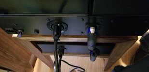
Picture of the amp connections attached. I've since made a shorter AC cord to connect the two chassis.
For my mono amps I have AC going into the amps with soft start circuits for HT and 833C filament and 6E5P heater supplies. I then run the 833C filament and 6E5P heater supply AC back out to a separate filament PS chassis using a standard 3-prong cable with the safety ground wire connecting the two chassis. The filament and heater DC then return to the amps via a 4-pole speakon. Dead quiet.
Picture of the amp connections attached. I've since made a shorter AC cord to connect the two chassis.
Attachments
Last edited:
In the picture above, the mains AC comes into the IEC outlet on the far left. The paddle switch next to the IEC turns on the filament, heater and 833 bias circuits, and the filament and heater AC then go out the AC connector on the back of the amps to the filament/heater chassis and the DC returns via the Speakon. All signal grounnds are in the main amp chassis, as are the filament and heater grounds.
The main 833C HT (2300V) is activated via a pushbutton on the front panel, after the filaments have warmed up.
The main 833C HT (2300V) is activated via a pushbutton on the front panel, after the filaments have warmed up.
Last edited:
Thanks Magz and Rongon, your comments are very helpful. I'm going to try out this:
- HT in separate chassis
- filament supplies and signal all in one chassis
So in the signal chassis the mains earth is connected to the chassis. The filament supplies are floating. The output filament supplies get grounded through the cathode resistor. The IDHT input DC will be grounded at a single star ground which also serves all the signal grounds.
Hope the above works. It's my preferred solution weight-wise. I'd like to separate the HT supply since it's heavy because of the mains transformer and choke(s).
Question: I've rewired my 6B4G amp as above. In the signal chassis there's no connection between chassis ground which is connected to mains earth and signal ground which comes from the PSU. Is this correct or should I think of connecting the two via come combination of resistor, diode, cap etc?
The way I've done it is
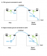
- Mains safety ground is a wire from mains plug earth wire straight to PSU chassis at the IEC socket. That's solely for safely grounding the chassis in case of short circuit. It shouldn't have any direct connection to 0V signal ground.
- 0V (signal ground) is connected to signal chassis at the audio inputs.
- Ground wire in umbilical connects 0V of signal chassis to 0V of PSU chassis.
That means that if you power up the PSU without the signal chassis connected, its 0V ground is floating.
I think that possibility of a floating ground with the PSU disconnected from the signal unit is a danger we have to accept. Perhaps put a bleeder resistor in the PSU to protect from that condition? (I'm not sure...)
--
Last edited:
- Mains safety ground is a wire from mains plug earth wire straight to PSU chassis at the IEC socket. That's solely for safely grounding the chassis in case of short circuit. It shouldn't have any direct connection to 0V signal ground.
- 0V (signal ground) is connected to signal chassis at the audio inputs.
- Ground wire in umbilical connects 0V of signal chassis to 0V of PSU chassis. That means that if you power up the PSU without the signal chassis connected, its 0V ground is floating.
-
Not sure I like the idea of the PSU ground not being earthed. But in terms of hum I don't like the fact that in the signal chassis there's no connection between the chassis and signal ground, though the chassis is earthed. Like you, I just don't know. I hope somebody does!!
I don't like the fact that in the signal chassis there's no connection between the chassis and signal ground
Sorry, I think I didn't describe what I was thinking very clearly.
The 0V signal ground should be connected to chassis at the audio input jacks.
It's the AC safety ground that's not connected directly to the audio signal chassis. However, yet another separate wire in the umbilical could connect the two chassis together.
I like to consider the two chassis as effectively ONE chassis with PS and signal components separated by some distance. As long as the two boxes are solidly connected to each other with a large enough gauge wire, that is true. In my preamp I achieve this through the DC umbilical. In my amps I achieve this through the safety earth wire of the AC cable between the boxes.
Also, why have a separate mains connection in each box? You can just connect one box to mains and connect the two boxes together in one of the two ways described above so they are both safety earthed.
Also, why have a separate mains connection in each box? You can just connect one box to mains and connect the two boxes together in one of the two ways described above so they are both safety earthed.
Last edited:
Strictly speaking, the AC safety earth connection should be bolted directly to the chassis with a double nut to prevent loosening, and nothing else should be connected to that earth connection.
Also, why have a separate mains connection in each box? You can just connect one box to mains and connect the two boxes together in one of the two ways described above so they are both safety earthed.
I need the mains connection in the signal chassis for the transformers feeding the filaments. If the filament supplies were in the PSU chassis then the signal chassis would only need the umbilical as you say. But then it would be necessary to run more cables from the PSU to the signal chassis. If only the HT is in the PSU chassis it eliminates the extra cables.
As you can see, there are multiple possible answers to this. Shame only you and rongon have picked up on this grounding challenge. Even if the convention is to put it all in one box, there must be many on this forum using 2 or more chassis. So what are they doing?
Yes !! And here's what I'm doing: 😀
I have a PSU / signal chassis split as well. (EL84PP)
PSU chassis generates B+, heater supply, and bias voltage.
PE is going directly to PSU chassis at the IEC inlet.
I then bring seven wires in an umbilical to the signal chassis:
- B+ and 0V return
- heater and return
- bias and return
- PE (the thickest wire in my bundle)
In my signal chassis,
- PE is wired directly to chassis
- 0V line of B+ is wired to chassis through a CL60 (10R cold resistance)
- heater is referenced to B+ / gnd as necessary
- bias is referenced to B+ / gnd as necessary
This way, I can use the PSU for different amps (signal chassis), as all referencing of the voltages from the PSU is done in the signal chassis.
If I recall correctly, I may have connected B+ gnd to the PSU chassis through another CL60 as well to not have HV floating around when the umbilical might be unconnected.
CL60 acts as effective hum breaker, but can transfer enough current in case of short to trip the mains fuse.
Regards, Claas
Last edited:
If you are building separable (by disconnecting umbilical) pairs of chassis for your friend and he is more listener than diyer/electronics thinker, I would seriously consider the possibility of using interlocks.
If I use two chassis implementation, exclusively put all PSUs to one box, and connect it to appropriate umbilical to amplification stage.
I use separated "safety ground wire" between boxes (connected to metal cases, if it available), inside the umbilical.
Each PSU is floating and connecting to each channel via umbilical.
The channel's "grounding" connected each other only in PSU box.
The "global" grounding point in the PSU box connected to "safety ground" point via 10R//100nF.
What is the purpose of this C60 - why a thermistor? And for euro21, why the 10R resistor and cap - what do they do for hum or otherwise?
Thanks!
Thanks!
The CL60 is used as hum breaker between signal ground and case / PE. Cold resistance is 10R, but when a fault voltage develops, the CL60 quickly heats up and gets very low resistance, and allows enough current to flow to trip the mains fuse.
Alternatively, you could use a big beefy 10R resistor (something like 10W rating), or a 35A-rated bridge rectifier that you parallel with a 10R resistor of lower wattage.
In normal condition, the 10R gives you a ground reference, but breaks ground loops that could cause hum, and in case of a fault, the bridge rectifier lets the fault current pass and again trips the mains fuse.
You can bypass the resistor / rectifier / CL60 with a 100nF capacitor to channel HF noise directly to case ground.
Have a look in the Pass forum here - we are using ground loop breakers like this all the time.
Regards, Claas
- Home
- Amplifiers
- Tubes / Valves
- How to ground an amplifier on 2 chassis?