Ok i have dual psu based on lm317/337 and it requires center tap transformer and it is all good. Now when I want to power something less power hungry i would like to use ac wallwart which i can easily find and its much safer than playing with transformer and also its much lighter. I need pcb or schematic of circuit that takes single secondary and provides +/- at output. I dont need more than +/-12v at output and 2A. It would be good if it is linear, i really dont want switching (i have found some dc to +/- dc on ebay but dont really know how it performs in audio). So i need AC-AC : +/-DC. 
I want this to replace big transformer. (Adapter in picture is just example i have different than this one)

I want this to replace big transformer. (Adapter in picture is just example i have different than this one)
Last edited:
Since you require 2A +/-12VDC bi-polar output the power brick that you show will not work. It shows only 500mA output at 12VAC. You will need more than 10x higher current output from the brick if you plan to use two half wave rectifiers to get +/-12VDC bi-polar output capable to deliver 2A of current.
Yea thats why i expained in text above picture that adapter is only example what i want to use to power my project. Will try this then My take on LM317 / LM337 power supply PCB
I dont really need 2a even 1A is more than enough, key thing is to eliminate mains wiring and exposed transformer i have now.
I dont really need 2a even 1A is more than enough, key thing is to eliminate mains wiring and exposed transformer i have now.
How much more elegant can you get?Use two AC wall warts wired in series
The Objective-2 headphone amplifier (sometimes called O2) does exactly what you propose. Its schematic is available online, do a bit of google searching to find it.
Mains --> AC wall wart --> 12VAC (2 wire barrel plug) --> circuit --> regulated ±12V DC and ground
The circuit is just a pair of half wave rectifiers (one for V+ and another for V-), followed by very large filter capacitors, followed by 3 pin voltage regulator ICs. Notice that the filter capacitors need to be twice as big for a half wave rectifier, than the caps for a conventional full wave rectifier such a four-diode bridge rectifier.
Your transformer is big to get the correct power for your amp.
The only way to get smaller is an SMPS which is what you say you dont want.
The only way to get smaller is an SMPS which is what you say you dont want.
My transformer is overkill for headphone amps and i find it not very practical so i want to use wallwart like in picture.
Yea Mark i need something like its done in O2.
If i dont find anything better ill use pcb from that Polish guy BamboszeK i linked, board seems very nice.
Yea Mark i need something like its done in O2.
If i dont find anything better ill use pcb from that Polish guy BamboszeK i linked, board seems very nice.
I like this layout better than wallwart.
This also happens to be an actual 12VAC 5A adapter, but it's prob not located convenient to you...
12 VAC, 5 AMP AC-AC TRANSFORMER | All Electronics Corp.
This also happens to be an actual 12VAC 5A adapter, but it's prob not located convenient to you...
12 VAC, 5 AMP AC-AC TRANSFORMER | All Electronics Corp.
Attachments

I like this layout better than wallwart.
This also happens to be an actual 12VAC 5A adapter, but it's prob not located convenient to you...
12 VAC, 5 AMP AC-AC TRANSFORMER | All Electronics Corp.
Very nice solution, I can get similar locally but I need pcb that will turn it into +- DC.
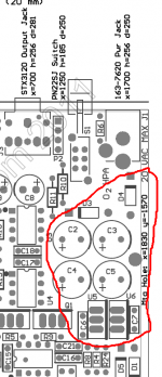
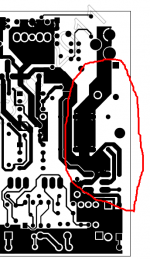
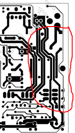
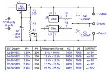
If you decide to build the 12VAC to ±12VDC circuit yourself on a piece of prototyping board (example), it's not a very large circuit at all. I've circled those components on the Objective-2 Headphone Amplifier board, look for the red circles. It's a small little island of a few components. Easy!
_
_
Attachments
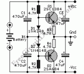
The circuit is just a pair of half wave rectifiers (one for V+ and another for V-), followed by very large filter capacitors, followed by 3 pin voltage regulator ICs. Notice that the filter capacitors need to be twice as big for a half wave rectifier, than the caps for a conventional full wave rectifier such a four-diode bridge rectifier.
That works fine as long as the load currents from the positive side and the negative side are not so different that it makes the transformer saturate - which is usually not a problem, because wallwarts with AC output usually have a simple EI transformer inside that doesn't saturate too quickly.
I always put reverse-connected rectifier diodes (typically 1N4002, although a Schottky would be better) from each regulator output to ground to ensure that the regulator of which the input voltage ramps up last doesn't go into latch-up. Otherwise, if for example the negative supply starts up first, the load could pull the output of the positive regulator negative, possibly triggering parasitic thyristors that make the positive regulator destruct itself.
- Home
- Amplifiers
- Power Supplies
- How to get dual rail psu from single secondary transformer